This is a placeholder topic for “Encoder Module with button” comments.
Round and round - measure rotational inputs with ease!
Read moreThis is a placeholder topic for “Encoder Module with button” comments.
Round and round - measure rotational inputs with ease!
Read moreThe specs for this product indicate 20 PPR. How many indents per revolution pls. I assume 20 would this be correct? Also where do the indents occur WRT switch operation although with use of a library where all the hard work takes place this probably does not matter.
Cheers Bob
Hi Robert,
As you’d expect, 20 indents. (20 clockwise clicks takes you back to where you started).
The pin marked “Key” gets tied to GND when you press down on the knob, and S1 and S2 get tied to ground momentarily when the switch is clicked to the next indent. They appear to be pulled up to VCC when not active, and there seems to be some hardware debouncing (RC filter) on board.
Hi James
Thanks. That answers that. Some encoders have the indents at different points particularly those that have twice as many indents as switch operations.
Probably similar to this one suggested in the Bourns data sheet

Cheers Bob
Hi James
A couple more queries
What model encoder is fitted. It looks like the Bourns PEC11 or PEC11R series. Which one is it.
What is the actual filter configuration or better still is there a circuit available.
Do you sell the board without the encoder. I have a suspicion it could be the PEC11 series. I prefer the PEC11R as this has a higher switching rating (10mA Versus 1mA) and a shorter bounce time (2mS Versus 5mS). If the filter is as the Bourns suggested circuit the 1mA might not matter as the cap will be discharged via the 10kΩ resistor which will limit current. If the cap is discharged without this resistor I don’t think PEC11 contacts would last very long (or probably any contacts for that matter).
Cheers Bob
Hey Bob,
From what I can find, the rotary encoder uses the PEC11R. The housing on the the unit matches that of the PEC11R and the length of the shaft matches that of the PEC11R and not the schematics I have seen of the PEC11.
It is worth noting though that this is one of our ‘Cheap and Cheerful’ products and so there is limited documentation for it available. Though I have put this to our team to get more information in the future and come back to confirm what this is for you so that we have some concrete information and not just speculation based on schematics.
Cheers,
Blayden
Thanks Blayden
I have had a close look at both data sheets and those 2 items seem to be the same. They look the same in the pics but you would think they had a different body colour or something. I will have a closer look. There are no markings so the 20 I got from Element 14 could be either. I suppose you have to trust someone. Unless repeated problems could be put down to either of these parameters what you are using could be either unless one goes into detailed measurement. I might actually try that.
What interested me is the on board filters. Far easier than using discrete components but it would be nice to know a little more about the configuration first. Might have to buy some and investigate.
That would not be speculation but pretty definite. Would answer most questions.
Cheers and thanks again Bob
Edit: Interesting that Element 14 no longer stock the PEC11 units, only the PEC11R types. Maybe bourns no longer manufacture the PEC11. That would make sense, why would they continue making the inferior type.
Hey Bob,
It seems from what I saw that Bourns are no longer manufacturing the PEC11 and have replaced it with the PEC11R, though who knows what other manufacturers are doing regarding this product at the moment. Would be interesting to know though if they are becoming less common in components that have previously used them and if there have been revision changes due to lack of supply.
Cheers,
Blayden
Hi Blayden
I have just checked the 2 data sheets again and the only differences I can still see are the switch current capability and bounce. The PEC11R being the superior specs. The PEC11R datadheet is the one I downloaded when I purchased so am pretty sure are the ones I have.
Checked the bounce performance as best I can on one unit. Pics follow.
The PEC11 data sheet I recently downloaded from Element 14 has the word “Obsolete” watermark stamped all over it.
I will order some of these units and just for interest remove an encoder and check it in the same manner.
Cheers Bob
Hi James, Blayden
As promised I have purchased a few of these units and have some observations.
A bit of sleuthing with a DMM showed the filter is the same as the one suggested by Bourns except for the Capacitor value. This seems to be about 150nF as measured in situ with a DMM. Actually measured a bit more but is approximate allowing for strays and measurement technique
Circuit:

The switch pins are pulled up via the two 10kΩ in series and the button pulled up by the 10kΩ R5.
This highlights another point which should probably be rectified. The example Pico sketch on your product page defines the button pin to be pulled up internally. This is not required as it is taken care of by R5. This has happened even though the text implies that pull ups are provided on ALL pins. A small error but one which could cause problems in some circumstances.
I am still running a couple of final checks which I will document soon. This unit seems to be OK for general use and has the nice filtering components built in to save a lot of hassle externally.
Cheers Bob
Hi Bob,
Thanks for sharing your insights, having a double-up on the pullup resistors will result in a stronger pullup than necessary but it should still be well within the Pi Pico’s ability to handle the current.
Let us know what the outcome of your final checks are.
Hi Trent
In that particular case it would not matter much. But if you look at the circuit carefully you will see that if you did this with the encoder switch pins they could never switch to ground as is the intention. The internal pull up would form the upper resistor value of a voltage divider with the 10kΩ filter resistor. A similar scenario could occur if an external pull down is used at the same time as the internal pull up.
With the home constructor any one of these situations could easily occur so I think the wise move is to make sure you never have both. Use ONLY internal or external. Could save a few headaches and lots of frustration.
Cheers Bob
Will post the rest soon. All rather interesting.
Hi All
As promised some results after my fiddles with module….
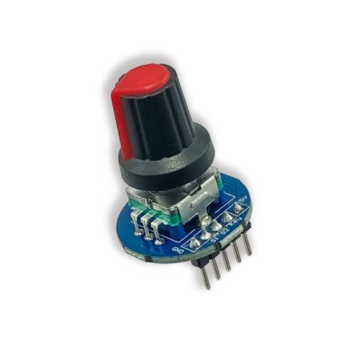
Encoder Module With Button…SKU…CE09436
I attempted to remove the encoder to observe switch bounce stand alone but I found the holes very small making it almost impossible to easily remove the solder so I left in situ. The encoder switches were isolated by simply removing the 150n capacitor to nullify the filter.
Once again it took a few goes to get any decent bounce pics and did not look too bad. Most bounce occurred between 0.5mS and 2mS.
Except this one which was nearly 11mS. I don’t any amount of filtering would prevent a miscount here.
With no filtering the encoder count is pretty hopeless.
Throughout these observations I used the following simple sketch with no attempt at software delays or filtering.
#define enc_a 2
#define enc_b 3

volatile int encoderValue = 0;


void setup() {
  // put your setup code here, to run once:
  Serial.begin(9600);

  pinMode(enc_a, INPUT);
  pinMode(enc_b, INPUT);
  attachInterrupt(digitalPinToInterrupt(enc_a), encoder, FALLING);

}

void loop() {
  // put your main code here, to run repeatedly:

}
    void encoder() {

      if (digitalRead(enc_a)== digitalRead(enc_b))
        {
          encoderValue++;

        }
        else
        {
          encoderValue--;

        }
      Serial.println(encoderValue);

    }
The next 2 pics are the a & b output with the filter as supplied (2 slightly different speeds of rotation). CW rotation.
There is a different in charge and discharge slope here due to the cap being discharged via 10kΩ and charged via 20kΩ. That means if the encoder is rotated fast enough the switches can close before the cap has fully charged. This would effectively shorten the discharge time when the switch closes and thus shorten any filtering effect which in turn could lead to miscounts. This can be improved by fitting diodes across R1 and R4 so the cap discharges and charges via 10kΩ and the cap has time to fully charge between switch actions. This is still not quite symmetrical as I used 1N4148s and the 0.7V forward voltage drop has some effect on the last couple of time constants.
With a “normal” slow finger rotation speed there is no noticeable difference in errors with or without these diodes but at faster rotation speed there is a difference. Strangely enough when rotated CW there are very few errors, an additional count of 1 every now and again but CCW rotation seems to add between 3 and 6 or 7 counts per revolution. I was monitoring the counts while rotating the encoder one full turn CW then CCW. While most CW rotations were accurate I could not get any CCW rotations accurate at all.
But, in the real world does this matter too much. After all if we are going for an absolute position we would (or should) be using an “absolute position” encoder. After all we are only comparing the new number with the old one and would normally just rotate the knob until it gets to where we want it to be. It becomes a real nuisance when it gets so bad the direction will change at random for no apparent reason or the output takes large jumps.
In Summary if you can put up with a little bit of error sometimes this is a very useful module. Having the pull ups and filter on an attached board is a convenient bonus. But I would like to see the diodes fitted to clean up the symmetry a bit. As I can show in the next episode by turning the encoder a bit fast it is possible to miss counts altogether due to the slow charging time. They could even be surface mount devices sitting on top of the resistors.
Next step will be an improvement by interfacing a schmidt trigger……To be continued………
Cheers Bob
Hi All
The ongoing quest for the perfect encoder.
Now I don’t know what sort of input signal the interrupt pins prefer, a fast transition or a sloping one, nor do I know at what point this triggers. Suppose I could look and find out but I thought a fast one would be nicer and a chance for some final filtering.
Enter the Schmidt Trigger. There are a couple of ways to go about this.
Use a dedicated IC. Some cons, most of the commonly available devices are inverting (probably not a big deal), they usually come in a package of 6 with 14 pins, the data sheets indicate a fair bit of variation in the hysteresis values, the reference point is not controllable….Pros, no external components required.
Use an OP Amp (in this case dual for switch a & b). Cons, external resistors are required….Pros, hysteresis is controllable, reference point is controllable, inverting or non-inverting take your pick.
The circuit I have used……

I have chosen the LM6482AIN, Dual low power, operating voltage 3V to 15V, performs quite happily at 3.3V. I have used 5V as it is connected to UNO R3, and is “rail to rail”.
The hysteresis is controlled by the ratio R5(R6) / R3(R4). Formula and handy calculator here…
https://daycounter.com/Calculators/Comparator-Hysteresis-Calculator.phtml
With the values shown this is 1.5V (1.75V – 3.25V)
The reference point is set by R1 & R2. In this case 2.5V
R7 and R8 are not necessary but are there for a bit of “insurance” in the case of accidents.
The outputs of the OP Amp are driven HIGH (source) and LOW (sink) so pull ups on the Arduino, Rpi or whatever are not required.
This Pic shows the basic operation with a sine wave input, the hysteresis can be clearly seen.
Next 2 pics showing the encoder filter output (yellow) and Schmidt trigger output (blue) for switch a, CW and CCW rotation. Did not investigate the little glitch on the charging curve but once again the hysteresis can be clearly seen and allowing for some measurement error is very close to the calculated value (little block top left of oscilloscope screen).
Next demonstrates what I mentioned previously. Rotating the encoder much faster than “normal” could result in missed counts, in this case 4, which I think would have been avoided with a diode across R1 & R4 in the filter network and thus a shorter capacitor charging time.
Next 2 pics show the schmidt trigger output for both switch a (yellow) and b (blue) for “normal” rotation speed for both CW and CCW rotation. Note nice clean pulses.
Using the schmidt trigger and rotating the encoder 1 rev CW and 1 rev CCW for several minutes produced 0 errors in the CW direction and an occasional 1 count error in the CCW direction.
Conclusion. If you can tolerate some errors particularly in the CCW direction this unit is fine as is. For volume control and similar where rotation would be relatively slow I don’t think this is a big deal as you would not be monitoring actual positioning and only rotating the encoder until you get it where you want it.
If you want or need minimal errors the use of a schmidt trigger as well as an RC filter is recommended.
If you need to rotate at some speed an optical or magnetic device would be needed anyway as the mechanical types have speed limitations (see data sheets).
I note with interest that of the few optical encoders I looked at on Element 14 quite a few had schmidt triggers built in and those that didn’t recommended using one.
That’s all folks. I hope this helps those contemplating using these devices in the future.
Cheers Bob
Hi Bob,
It certainly will! I like that you’ve included scope plots that show exactly what’s going on and why you’d want to set this up the way you have ![]()
Returning to this topic.. after upgrading from a Pico to a Pico 2.
I was using Peter Hinch’s async driver, but nothing worked on the Pico 2. Have been in discussion with Peter, and also tried the portable driver from his excellent repo here Not having much success.. so, I am wondering if others have used this device on a Pico 2 with his driver.
Note: using the basic IRQ that simply compares pin values works… the issue is Peter’s more sophisticated drivers (mostly) don’t work at all (ie NO interupts seen at all) on Pico 2. Confirmed with scope traces… pin voltage drops, but the IRQ does NOT fire.
In diagnosing this issue, I have noticed that putting a 1K external pull-up really messes up the pin dropping to ground… it doesn’t get aywhere near 0V. This pull-up was suggested by Peter, who confirmed his portable driver works just fine with 1K on both Pico and Pico 2, but then he probably has a different encoder - not the one from Core (he resides in UK…)
I have not (yet) implented Bob’s Schmidtt trigger, but I may do as I have a spare couple of spare LMC6484 circuits on my board, but this post is NOT about eliminating contact bounce. Thing is, it appears that the onboard debounce logic may be responsible for interfering with Peter’s async driver, and his portable driver. Interesting, his RP2 driver, which uses PIO code, half-works. The machine.Pins class on Pico 2 is I think still a work-in-progress!
Anyway, just putting it out there. I am moving away from using the encoder in my project… my UI is better controlled with a 5-way navigation switch, so this is kinda academic for my immediate needs.
Cheers,
T.
I’ve just pulled out our test Pico 2 and tried it with the example script on the product page with no success, I did though get expected results by adding an internal pulldown, to the encoder pins.
Interestingly the code worked out of the box with the original Pico with no issues so there has definitely been a change between the generations.
Hi Dan
We are talking about the same product here are we not. Namely SKU CE09436.
The units I have have pull ups on the output pins which are pulled low by the encoder switches. I just can’t see where an internal pull down resistor would make anything work. Unless you are applying 5V to the encoder board which would appear on the Pico input and the Pico is getting upset about this. A pull down would form a voltage divider with the pull up on the board and get the 5V down to a level the Pico can handle.
If this is the case the solution would be to apply 3.3V instead of 5V. Makes no difference to the encoder as all the components are passive and not voltage conscious.
The screen print on that board does say “5V” which is a bit naughty and confusing. As this board is completely passive it makes no difference to it if this pin has 5V or 3.3V. Maybe it should read “+V” and remove confusion.
Cheers Bob
Indeed, the ref to “5V” probably should change.. I did indeed have VBUS routed to my breadboard, and consequently, was presenting 5V to the GPIO pins… which is not kosher.
And yes, Dan… that script on the product page works for me also on both Pico 1 and 2
That said… I have a heap of testing with a scope, and various permutations of Pico 1/Pico 2/internal & external pull-ups.
In summary, what I found is:
The sample code on Core’s site looks like OK… Pin.PULL_UP is ONLY applied to the switch pin, not the rotaries, so that’s fine. At some point I must have changed my code to include the internal pull-up on all encoder pins… It worked on the Pico 1 using Peter’s async driver. And broke when I replaced Pico 1 with Pico 2. So… caveat emptor… it appears to me that there is some strange interaction with this encoder’s RC debounce logic and Pico 2 internal pull-up circuit, that does NOT apply to the Pico 1.
If I was going to persist with the encoder, I might employ Bob’s Schmidtt trigger stuff…but
Cheers,
T.
Just surfing around and I found this, which hints that the pull-down is not working as expected in the Pico 2;
And you can get our latest projects and tips straight away by following us on:
![]()
![]()
![]()
![]()


