What calibration proceedure ? Ah, I found it in the Arduino section on DFRobot’s product wiki page. I know that ESP32 is based on Arduino and can be programmed with their tools - but I come from a software background so jumped straight to Raspberry Pi in order to avoid the low-level Arduino code. So no, I haven’t followed calibration procedure, but that section states that without calibration the maximum error is 3%, and I’m not sure that it would be possible to do without going down the Arduino software rabbit hole.
More significantly, it sounds as though everything Robert and Jeff have suggested assume more electronic expertise than I actually have … and a working multimeter which measures current - which mine appears not to.
And you seem to be arranging the deck chairs on the Titanic …
What is important to me is that the current from a 5V USB phone charger gives a significant increase in battery charge (per the left side of the above graph) - but when the SEN0291 is inserted in the USB cable from the same USB charger, the SEN0291 is not even passing enough current through to maintain the battery charge. To my untrained mind this is not measuring the current - but seriously limiting the current.
The graph above is not the readings from the SEN0291, but the Battery voltage going up, and going down with the SEN0291 in place. THERE IS NO DECIMAL POINT in that graph.
And what actually are you suggesting ? Remember that I am not an electronics engineer and most of your instructions are way over my head.
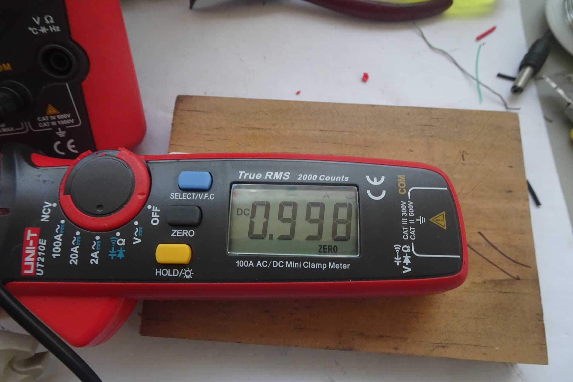
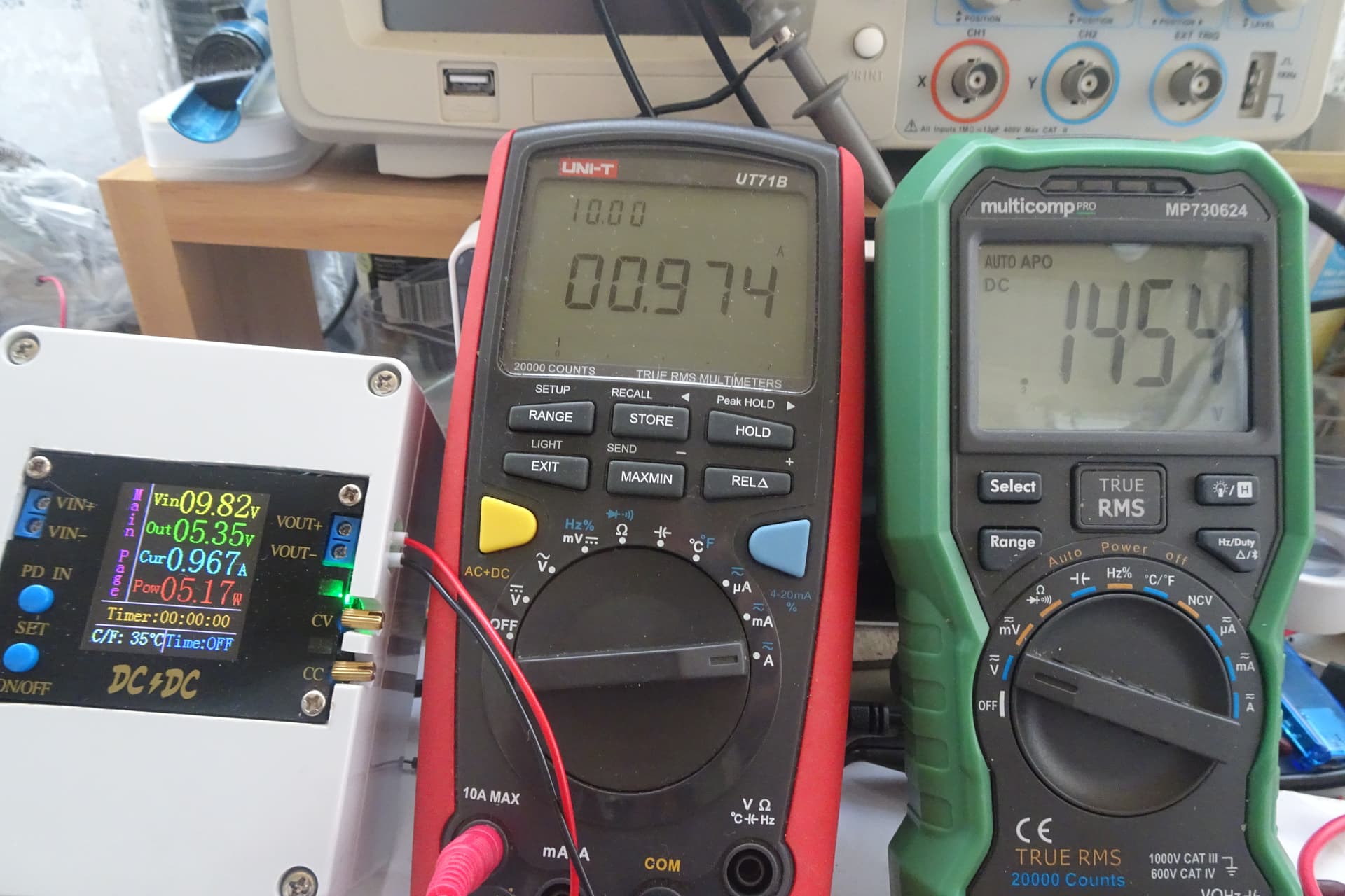
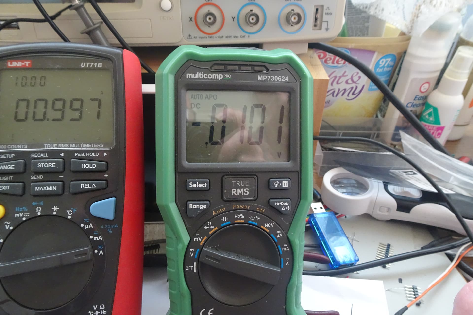
Use a multimeter, OK. I did mention that my multimeter doesn’t seem to be reading any Amps.
What does this mean ? How can I measure current without connecting a multimeter ? Where should I connect it ? With power on or off, or SEN0291 totally disconnected ?
Which is the shunt resistor ? Is it the larger box labelled R010 ?
What is “DMM” ? Do I already have one, or is it going to be more delay and expense ?
What is considered “OK” ?
Again, I am not the Electronics Engineer / C programmer you assume me to be. And my goal is NOT to become an electronics engineer - just to determine whether the SEN0291 is faulty.
I feel the same about having to learn Arduino as you do about ESPHome.
Totally unrelated, but I don’t imagine many users would not want to measure battery usage and voltage, and solar panel input … so why not build these monitors into the Solar Power Manager boards ? OK that doubles the cost, but building into one board would be cheaper and so much more convenient.
Why ? I am hoping to leave my greenhouse unattended for several days at a time. The DFRobot Power Manager and MAX17048 combo has run my battery flat, several times - so they can’t be trusted, and will need to be monitored. For now I’m still feeling my way, wondering how big a solar panel and battery I will need. How will I know how much money I need to spend to allow the system to run for 3 days during a rainy winter … if I don’t monitor anything ? I don’t see it as an unnecessary luxury.
What is so wrong with a 5V USB phone charger ? It’s not as though I can use the phone charger in the greenhouse, and the Solar Power Manager has a 5V input socket.
Is this going to actually prove anything, or just an opportunity to spend time and money creating a one-off circuit ?
And if it does turn out to be a 10mΩ instead of 100mΩ ? How does that fix the amount of current flowing through the SEN0291 ?
So you still don’t see any difference in the battery voltage graph ?