I have a DFRobot DFR0457 MOSFET module where there is this information:
for projects involving inductive loads like motors and solenoids to use a freewheeling diode to prevent back EMF damage. This module is a critical component for anyone looking to expand the capabilities of their MCU projects.
How do I properly add a freewheeling diode to switch inductive loads (motors, electromagnets, relays)?
Where and how should I correctly insert a protective diode to protect the module, and what is the best diode for this purpose?
Across an inductive load, Motor, Solenoid, Relay etc. Cathode to Positive side of load.If you could provide a schematic of exactly how you intend to set this up we could be more specific.
Depends on the load. Current capability should be at least the stall current of a motor or the operating current of relay/solenoid.
Some use power diodes like the 1N4xxxx series but I don’t think they are fast enough. I prefer a fast schottky diode personally A diode often used in motor speed control is MBR20100CT. This is a dual diode TO220 package and it is usual to connect both diodes in parallel which gives a capability of 20A. Usually enough for most applications and is a tried and proven device for this use.
Cheers Bob
I have come across conflicting information and I’m not sure which version is correct for protecting a MOSFET module with a diode.
I have this MOSFET module and an SB5200 diode (I assume it should be sufficient for relays and other loads up to about 5A).
I made two versions:
Version 1: VIN (cathode) – VOUT (anode)
Version 2: GND (anode) – VOUT (cathode)
I’ve seen different recommendations in various places online, and now I’m not sure which configuration is correct for adding a freewheeling diode to protect a MOSFET module.
Could you please clarify which version is the proper one?
Hi Martin
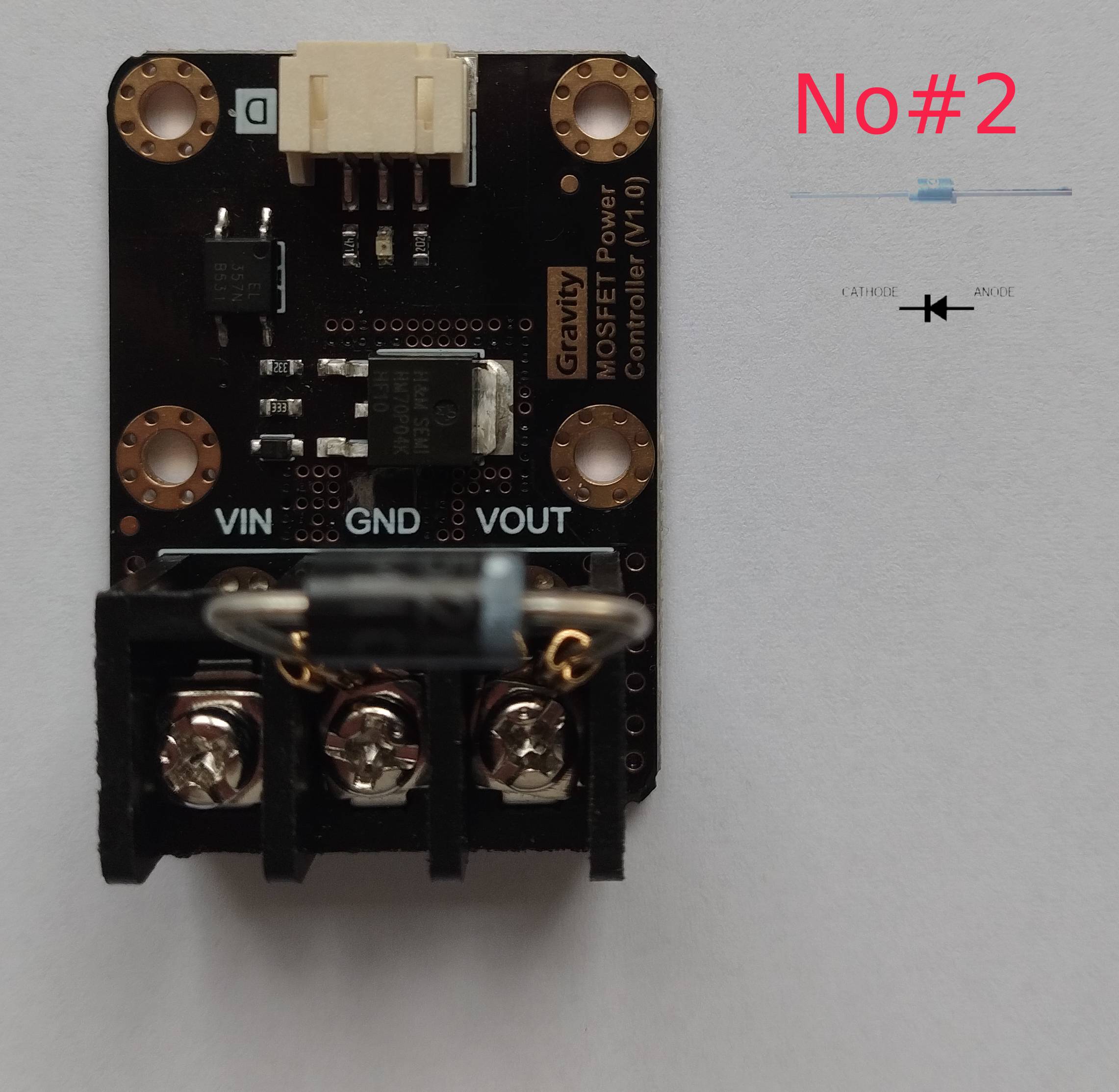
NEITHER. Especially NO#2. This would result in the switch being completely bypassed and remain apparently ON at all times.
If you read the above properly i did say ACROSS THE LOAD.
You have connected it ACROSS THE SWITCH.
This is only needed for INDUCTIVE loads. Resistive loads such as lamps, heaters etc don’t need it. but adding this to all loads does no harm
The “Load” in your case would be anything connected between Switch Vout and negative supply and the cathode would connect to the positive side of the load which would be the Switch Vout.
Cheers Bob
Hi Martin
Edit to last reply.
Very sorry but pic NO#2 looks at first glance as if the diode is connected across the switch.
Closer inspection sows the diode connected between Vout and ground.
If the load (relay, solenoid etc) connects directly between Vout and ground this is correct. The diode is the correct way around.
It is pretty unlikely but if there is anything between the negative side of the load and ground the diode will have to be connected directly across the load. This has to be where the diode is connected irrespective of anything else. The diode is there to eliminate the opposite polarity voltages generated when the magnetic field present in an inductor such as relay solenoid etc collapses rapidly at switch off. This could be several times the normal operating voltage of the inductive device.
That diode should be OK for small to average loads. For large high current loads the one I suggested might be better. Loads up to a couple of amps should be OK. As I said the reverse voltage generated could be several times the operating voltage and the same applies to the current that has to discharge via the diode. The steady current is quoted at 5A with a repetitive pulse current of 20A. If your operating current is near 5A I would think this diode would be border line and I would opt for the one I quoted which has a rated steady total current of 20A (10A for each device in the package).
Perhaps I am not fully understanding your explanation because my English is not the best ;-(
Therefore, I would like to refer to your statement:
“If you read the above properly i did say ACROSS THE LOAD.”
The only practical solution I can think of is placing a diode in series and connecting the load to it. In that case, the reverse voltage spike generated when disconnecting a motor or relay (an inductive load) would not reach the MOSFET.
So, is this configuration correct, and is this the solution you were trying to suggest?
In your second message, you wrote that the method shown in picture #2 is correct, so it seems that solution can be used. However, I would like to refer again to your statement:
“If you read the above properly i did say ACROSS THE LOAD.”
Is the circuit I am showing now in the picture actually the solution you are suggesting as correct?
If the schematic is still incorrect, please edit the image and show graphically the correct solution.
You suggested using a more powerful BR20100CT diode, but I currently have an SB5200 at home. Once I understand the correct placement and use of a 5A freewheeling diode, I will know how to properly use the 20A diode, which has three pins.
Hi Martin`
No that will not do.You need to get rid of that reverse voltage and current in the coil windings.
I should have done this in the first place. A quick schematic.
The “electronic switch” connection is the Vin, Vout terminals of your DFR0457 switching device.
If your inductive part of the load is up to about 2A the diode you have will be fine. It should be connected as close to the inductance (relay, solenoid etc) as practical to keep the discharge current out of the general wiring where it could cause problems. This keeps it in its own little circuit through the coil, diode and back to coil. It is only required across the inductive parts.
If the inductive operating current is more than about 2-3A then this is where I suggest the larger diode.
Dual diodes in one package, common cathode.
In use connect the 2 outside pins together (pin 1 and 3) this becomes anode and will effectively connect 2 diodes in parallel
Hope this clears this up.
Cheers Bob