Thanks for the testing and confirmation @James
Hi Andrew
Sorry for being a bit late
I don’t think this would be very feasible. You would probably need Farads (plural). If you look at discharge curves you will see that a capacitor loses voltage very quickly. Although a large cap would take some time to completely discharge the voltage would fall below RPi threshold very quickly. Devices which use cap back up usually will operate down to very low voltages.
There is a possible simple solution.
Get yourself a couple of Schottky diodes. Schottky because of the lower voltage drop, try to get 200mV or less. 10A twin pack units are available and you would need common cathode.
Power your RPi with your permanent (12V battery ??) supply (at the 5V level) via one of them.
When the time comes connect your temporary supply (5V) via the other diode.
Then simply disconnect your main supply and re connect when your set up is complete.
This will enable you to disconnect and re connect either supply without interference as long as one remains connected and has enough capability all will be OK.
This Diode OR technique is used to use several supplies (I have had to use 3) for almost complete redundancy such as a military installation where continuous power is paramount. Plus battery back up if it is really important.
Cheers Bob
4 Likes
Genius, I cant believe that I didnt think of this, this is exactly how I used to run a multi-battery hot swap battery bank.
I have a huge amount of Schottky diodes here already, so I will give that a go.
Thanks for pointing in the right direction.
2 Likes
The only part of the solution that it wont solve using Schottky diodes is that I have to disconnect the boost part of the power after connecting the 12v power (rectified to 5v). That’s not the end of the world, but it does mean that I cant run it in the way that I wanted, which was to plug external power into the boost to charge the 18650s AND run the pi at the same time.
That’s not too bad, it just means that I need to have the 18650s charged and ready to go ahead of time, power by the boost converter and batteries, do the setup, pack it up and move it.
When it is time to switch to the 12v power, connect it then disconnect the boost and battery.
The outcome is the same, just not that elegant, but at this stage it’s the best that I have.
2 Likes
Hi Andrew.
You are very welcome.
That is exactly what I had in mind. You are having so much trouble here it seemed to me to be the simplest and most practical way out. I am sure the RPi should be able to handle the 200mV drop. If it can’t I myself would be looking at something else.
Might not be that elegant but has been proven to be very reliable over time. Used in many high reliability installations, including the Air Traffic Control system on which you entrust your life to whenever you fly. This is a situation where “hot swapping” is not only desirable but absolutely essential.
Cheers Bob
2 Likes
I agree.
I also agree and I am kicking myself as I’ve built this solution myself before.
2 Likes
@James I notice on a bit of digging that core has the DFRobot version of the PiJuice, without battery.
Are you able to confirm that it provides power to the Pi when running off battery then adding charge power to the HAT, as well as then removing the power?
It looks like a reasonable facsimile to the PiJuice without some of the fancy features or battery, not fancy price tag.
thanks.
2 Likes
Hi Andrew,
I’ve done some bench testing with the Pi UPS HAT and our largest 2pin battery pack and confirmed it was quite happy with me disconnecting and reconnecting the charger (official Pi USB C supply) without interruption.
Interestingly, we also had another shipment of the MP2636 Power Booster & Charger Modules arrive so I’ve tested one of those too to see how it handles supply interruption.
The MP2636 was quite happy supplying the Pi with just the battery connected but when I switched on the supply (official Pi USB micro supply) the Pi started to show a low voltage warning. The Pi board didn’t totally lose power at any point but I suspect what is happening is the output voltage has sagged under the load of running the Pi and charging the battery simultaneously.
To test this theory I repowered the system with the battery removed and the power supply, via the booster & charger module was able to power the Pi without the low voltage warning which would suggest the combination of charging and powering was too much for the module (or the supply) and caused the voltage sag.
3 Likes
That is very interesting.
I just tried it again on a Pi 2 and it seems to work perfectly.
I dont have access tot he Pi 4 and screen right now to have another try, but will give it a try next week and see the result.
It might be that if you are drawing under the 2A it works fine without dropout.
Thanks for the testing!
3 Likes
No worries, I’d be very interested to hear your results. I threw the biggest capacity battery I had at it and only a USB keyboard and mouse for peripherals so the current draw was definitely minimised, though the Pi4B alone can draw quite a bit.
3 Likes
Hi @Trent5487676 I just tried this and using the Pi 4 and HDMI screen, powered from the Pi, unplugging or plugging in the charge voltage sag it too much and the pi reboots.
I’ve tried double feeding it with the DFRobot 4x18650 battery pack and it still cant make up for the voltage sag.
OK solved it ![]()
The external screen draws too much voltage to account for the voltage sag.
If I turn the screen off and plug in or remove the external power, then turn it back on a few seconds later, the Pi is still running no issues.
3 Likes
Hi Andrew,
Interesting, if the converter is happy running everything at steady state and only fails with the screen connected during a supply interruption then it seems to be an issue primarily with the transition between states.
As a student I lived in a sharehouse that had far too many appliances on too few circuits. The circuit breakers would trip all the time but if my desktop computer was connected when the breaker was reset. The inrush current to the large 1200W power supply, alongside the rest of the house was too much and caused it to immediately trip again. The process was to remove the computer, reset the rest of the circuit, then reintroduce the computer.
Ideally, we’d like to find a portable power supply that could handle everything you threw at it and wouldn’t need this kind of careful load management but it means the supply needs to be somewhat oversized so that it can cover those worst-case scenarios of inrush current.
1 Like
Further to this, I am using 2x18650s as the power source, in parallel.
If i leave them charging via the MP2636 until the charge light goes out, then I can remove the power and it runs with the screen until I plug it back in and there is no dip or loss of the Pi, however the screen does dim.
That doesnt seem to be totally stable however, sometimes when doing that it will drop the pi.
I can now say exactly what is happeneing with the power consumption though as per @Robert93820’s suggestion I bought a USB power meter.
the Pi 4 without the screen, running my custom Pi Hat, Apache and Python Scripts, but not trying to do anything, is using 0.6 - 0.7 A and 3.2W - 3.4W.
With the screen powered on, it uses 0.8A - 1.1A and 4.1W - 4.6W.
I wouldnt have thought that that was an issue to handle, but it is that minute lag in Watts on the change of status of plugging/unplugging the input power that is the issue.
3 Likes
I dont like to keep dragging this up, but maybe one day someone will get some good information about my trials and tribulations.
I thought that I had it all worked out.
- Power the MP2636 by USB and have two 18650s connected to battery in parallel, and the output going to the Pi, with the HDMI screen connected.
- turn off the screen
- unplug the micro USB connection to the MP2636 so that it powers the Pi by the battery
- wait a while. this is to simulate my use case.
- re-plug the micro USB to the MP2636 so that it doesnt need to rely on batteries any more
- turn the screen back on
This worked 100% of the time without any issue in my test setup which meant that the micro USB powering the MP2636 was coming from a plug pack plugged into the wall.
However, if I run this micro USB from a 12v battery with a DC-DC Buck converter at 5v, then it reboots the Pi every time that you re-plug the power back in.
NOW Im scratching my head.
The DC-DC Buck converter is outputting plenty of power as per the USB power meter, I know that the MP2636 is only drawing half a watt.
In fact I know that the DC-DC Buck converter can output enough to power everything as the Pi and Screen run perfectly happily from it’s output.
Ive tried using eh same cable, different cable, hard wired, every different combination, but always get the same result, the pi reboots on plugging the power back in.
The only thing that I can think of is that when the DC-DC Buck converter is re-powered that it must be either putting out a spike of inrush power that is >5v and causing the pi to reboot, or that it is unstable on startup and sags prior to providing the correct power.
Shoudl I be trying a capacitor across the outputs to try to smooth the power?
1 Like
Hi Andrew
Exactly what do you mean by that. Are you plugging the battery into the buck converter or is this connection already made and you are plugging in the micro USB connection. The buck converter may likely have a large inrush current. Difficult to measure with Digital meters. Storage oscilloscope really the only way.
Not a good idea without knowing exactly what is going on. You would need thousands of µF and this itself would present a short circuit until the cap is fully charged.
You could theorise forever about this without getting very far. What happened to the simple 2 schottky diode approach.
Cheers Bob
1 Like
Maybe this will help.
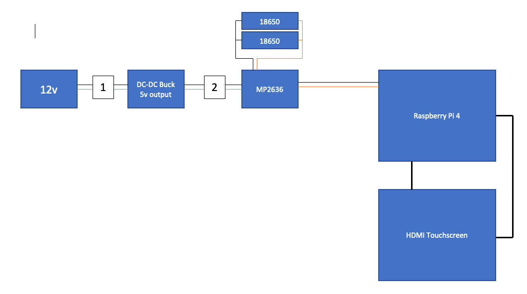
in this arrangement the Pi and Screen will run no problems at all, and this is the long term running setup that I want to use.
If I remove the power connection at point 1 in the diagram, the Pi will not keep running, and goes into a reboot loop. I dont know why, as I said earlier, the Pi and Screen are only drawing around 1.1A max.
If I turn the screen off, then remove power at point 1, then wait a few minutes, then plug point 1 back in (without the screen being on) then the Pi still reboots.
However…
If I turn the screen off and disconnect at point 2, wait a few minutes, then reapply the connection at point 2, with the screen still off, then turn the screen back on, the Pi stays powered on.
My issue with this setup is that it wont work for me without having to have two 12v cables as there are other 12v devices connected to the pi that I need to still power.
The whole point of this arrangement was to have a single 12v supply.
Sorry If I have been confusing, there is a short term need and a long term need, and I am trying to solve both of them at once.
Yes, the short term fix is more than likely the schottky approach, however long term it needs to be really simple, self contained battery solution.
I would need to change to a 12v internal battery in order to do that, and the requisite charging capability. (that is actually a possibility)
2 Likes
Hi Andrew
Yes it certainly does.
I think what you need to do is monitor the behaviour of the MP2636 output. You will need an oscilloscope as any other instrument will not be fast enough. From what I have read (nil practical experience) the RPis are a bit voltage conscious and it does not take much for them to stutter a bit.
Also have a study of the graphs in the data sheet. At battery or 5V input application there are some delays to the output indicated which range from 4 to 5msec. This may be where the problems arise. It may be that while the change over would be OK in normal circumstances under a bit more load there may be some sag, enough to reboot the RPi. In this case your system would not be a true UPS system if there is any slight sag in output voltage. I sometimes get the impression that the RPis are a bit fragile in this regard.
Somewhere someone suggested that charging systems are not designed to charge while the batteries are under load as the load interferes with the what the charger sees as the true state of the battery. This statement would be valid and if there is indeed a slight delay between battery and 5V supply this may be your problem. Without the screen the load might be light enough for the output to hold up and connecting the screen might be the proverbial straw on the camel’s back.
Observing what is happening at the MP2636 output (under load) will tell you lots.
Cheers Bob
Still think if you want a true “no break” system under load you will finish up with 2 diodes.
2 Likes
Yep, that part is beyond my test hardware capability unfortunately, as well as my technical ability.
The clear issue that I have with the MP2636 is that it isnt designed to do what I want, it’s not a UPS controller.
I know that, however I was hoping to be able to change something in order to rectify that.
Yep, I understand that that is the definitive solution that will absolutely work, however it doesnt fit with my requirement.

That is an old setup, but the gist is the same.
Raspberry Pi controlled camera rig for timelapse sequences.
I pretty exclusively shoot multi day sequences now, so require an external big battery so that is can power the Pi, the add on custom board, three DC motors, camera and dew heater. It wont run long enough from a battery mounted with the Pi.
Between setups I dont want to turn the Pi off, I want to unplug the main battery and have the Pi maintain state until I can plug it either back into the big battery or to a 12v supply form the wall.
All that will work with the diode solution, however it means that I will need to monitor and maintain the internal battery charge state. In the way that I have it almost working now the internal battery is always charged as when running from the big battery it is also charging.
2 Likes
Hi Andrew
We may be thinking at cross purposes here.
What is this “internal” battery. Here is a sketch of what I had in mind. I think we were on the same page a while ago but you now seem to have an “internal” battery.

You still use the 12V battery and buck converter.
You retain the MP2636 to
- Charge the 18650 batteries
- provide the boost to 5V to run the RPi.
But NOT both at the same time.
My idea was as you surmised to only use the 18650 plus booster when required to keep the RPi alive while disconnecting the main battery supply. Then restore the main supply before removing the back up for recharging. At the moment I think this is your best bet. There is no need for a second 12V supply.
Cheers Bob
3 Likes
Thanks for the diagram, that is what I thought that you were proposing.
When I referred to ‘internal battery’ I was talking about my camera gear, and the fact that I want it to have the backup power ‘internal’ to it, ie in the same case.
I meant that that was the MP2636 battery.
The issue with the setup as you have diagrammed is that I would now have an external to my device battery with lead that would not be part of it. I’d need two power sockets on my device.
There’s no point at all having the MP2636 in this instance as I can just use a 12v small battery.
I totally agree that that would work, but as I said previously, it’s a clumsy user experience.
Noted that everything else that I have had to date is equally as clumsy ![]()
Driving home tonight I thought about just going for a 3s BMS and use 3 x 18650s and use the buck converter to make that nominal 12v the 5v that I need.
I’ll be able to input the charge voltage to the BMS at any time and draw the 12v nominal out of the 3s pack.
2 Likes