To whom it may concern,
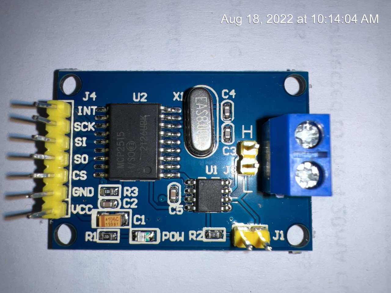
Sorry to trouble you… I was hoping you could advise on the correct wiring diagram for the MCP2515 CAN Bus Module Board TJA1050 receiver (Accelerometer).
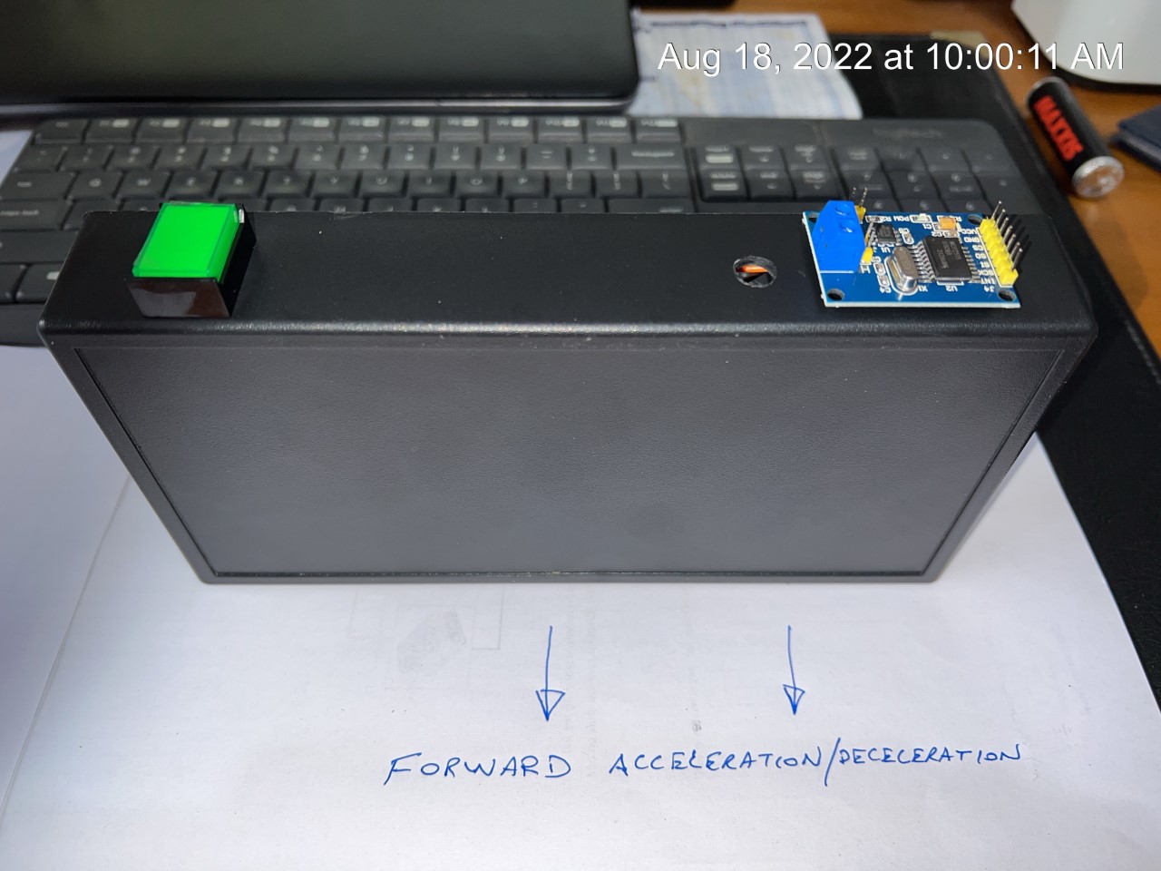
In my case I am only going to use this accelerometer receiver card in my Lascar SGD 43A brake test instrument to measure the Zero speed stopping reference in the forward motion after undertaking a brake test.
Normally, the MCP2515 CAN Bus Module Board TJA1050 receiver is integrated as a SPI Interface for communication with microcontrollers. In my case I don’t want to use a microcontroller due to the additional processing time which is critical when calculating the m/sec² during a brake test.
Questions
Which pins do I need to connect to obtain the 1.5volts dc reference for 0 speed (0km/h).
What is the correct orientation of the card when installed in my meter. (Parallel to the ground with the pins and connection to the sky? Which face of the card needs to be facing the forward motion?) Note: I was planning to install the TJA 1050 receiver card on top of my enclosure in a mini enclosure on top with the card positioned as in the photos with the main enclosure top face parrael to the ground plane. (Please refer to attached photos)
I believe that the blue screw terminal termination connector is for the 5VDC supply. (H = + 5VDC, L = GND -0VDC return
Appreciate if you can advise and thanks for your support.
Regards
John Oste
johnoste@live.com.au