This is a placeholder topic for “Kitronik Robotics Board for Raspberry Pi Pico” comments.
Make the Raspberry Pi Pico the core of your new robotics project with the Kitronik Compact Robotics Board for Raspberry Pi Pico.
Read moreThis is a placeholder topic for “Kitronik Robotics Board for Raspberry Pi Pico” comments.
Make the Raspberry Pi Pico the core of your new robotics project with the Kitronik Compact Robotics Board for Raspberry Pi Pico.
Read moreThis question is regarding the Kitroniks Robotics Board for the Raspberry Pi Pico. I have a supply voltage of 10V to the board, and several servos attached that require 6V. From what I understand, I will need to use a 6V voltage regulator from the Servo Voltage pin to the Servos.
What I am unsure about is whether or not I need to also add a 6V voltage regulator from the signal pin to the servo?
Hi Peter,
The board supply will go straight to the servo connections and motor supply.
There’s an onboard servo driver that will handle the boosting of the data lines for each of the servos.
Hi Peter,
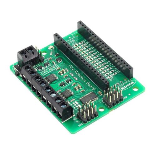
Great question. I’ve taken a close look at one and confirmed it’s pretty much a direct path from the power input screw terminals to the “V” pins for the servos:
The only components you see in the path are likely MOSFETS
So if your servos can only handle 6V, you’ll need a 6V supply or regulate it down:
https://core-electronics.com.au/catalogsearch/result/?q=pololu%206v
Hi Peter.
I would think not. Liam and James have established that there is a direct path from the “Power” terminal block to the V pin on the servo connectors. My thoughts are that this “Power” block is for motor power be it stepper, brushed DC or servo and the rest is taken care of. So in your case connect the required 6V to the “Power” block then just connect the servos as normal using the 8 X 3 servo pins. You should convert your 10V to 6V BEFORE connecting to “Power” block. Just make sure the converter (and main supply) has enough grunt for worst case, all servos operating at once. The Pico is powered via a 3.3V regulator on board.
A hypothetical scenario. What do you do if you need to run a mixture of motors requiring different voltages??? Could get a bit messy.
Cheers Bob
Thankyou for your input everyone. It has been incredibly valuable and I have been able to utilise several components very successfully.
I am writing this now as for some reason I can’t make a new thread regarding this product for this different question:
Hello, I am having issues with running a stepper motor on this board. I am using a 17HM15-0806S at 6V (in bipolar series i.e 4 wires instead of it’s 6). It runs at 8 RPM but my use requires upwards of 200RPM which I’m having trouble achieving. I have tried modifying the speed value (original is 20) in the PicoRobotics module (which I assume changes the pulse length) but it has not increased the speed at values of 50 (doesn’t run), 40, 30, 10, 1, 0.1 and 0.01. I have 2 stepper motors of the same type and they both are stuck at this very slow speed.
I have recently run this on a different motor driver and was able to speed the stepper up to 300 RPM reliably before losing precision, so it is not a problem with the stepper motors, but rather the code.
Your assistance will be greatly appreciated ![]()
These are the coding modules I’m using:
PicoRobotics.py is mostly unchanged, except for StepsPerRev=400 instead of =200. (Kitronik-Pico-Robotics-Board-MicroPython/PicoRobotics.py at main · KitronikLtd/Kitronik-Pico-Robotics-Board-MicroPython · GitHub)
main.py is as follows:
import PicoRobotics
board.stepAngle(1, "f", 36000)
# Stepper 1 (Motors 1 & 2), Move forward (clockwise), 36000 degrees (100 rotations)
Thankyou ![]()
Hi Peter,
I’ve had a look through Kitronik’s example code and in the comments the author has written:
speed sets the length of the pulses (and hence the speed…) so is ‘backwards’ - the fastest that works reliably with the motors I have to hand is 20mS, but slower than that is good. tested to 2000 (2 seconds per step).
It’s sounds like you’re running at the same max speed the author was able to test with when they wrote the code. I’m not sure yet where that 20ms limitation has come from, but there are a couple of candidates. Something will be running with a frequency of 50Hz (which corresponds to our period of 20ms). The I2C bus on a Raspberry Pi Pico runs in the 100s of kHz, so we can rule that out.
UPDATE: I’ve had a look at one of the modules we have here on the shelf and it seems like there is a PWM driver chip between the Pico and the motor driver chips. It’s likely the PWM chip is being set up with a 50Hz carrier wave, so the driver chips can’t be told to run any faster. I’ll see if @Michael can work out if there is a way to re-configure the PWM chip to raise the upper speed limit if that is the cause of the bottleneck.
Hi @Peter242324! I may have found something to try.
This device uses a PWM chip (PCA9685) to generate signals appropriate for driving servos. The chip is also used for driving motors/steppers.
Servos are generally driven by a 50Hz pulse wave which is where the author’s note about a minimum delay of 20ms comes from - they appear to have hard-coded the prescaler such that the 50Hz frequency is constant and applied during initialisation.
This fixed 50Hz is fine for servos and DC motors but will determine the maximum speed a stepper can run at.
Try editing the file so that line 11 which reads
PRESCALE_VAL = b'\x79'
instead reads:
PRESCALE_VAL = b'\x03'
this all comes from the PCA9685 datasheet
EDIT on second thought, 1526Hz is actually bonkers
maybe try something more reasonable using the above formula. Try something close to the existing 50Hz and work up from here. 50Hz is still pretty fast!
By the way, the speed= argument is a delay, so smaller values mean a faster motor speed.
the original 50Hz is 50pps (pulse per second)
at 400ppr (pulse per revolution) i would have expected to see a stepper speed of 4 revolutions per second, not 8 revolutions per minute.
closing thoughts
(If I’m interpreting this code correctly) this may not be the right product + driver code for an application that needs to drive a stepper motor continuously. It looks like the code is totally blocking - the step() method is using a while loop to drive the stepper, meaning the code is totally occupied whilever the stepper is moving. Furthermore, it seems to me that every step requires an I2C transaction.
Driving stepper motors looks like more of a nice little bonus feature of this product rather than the primary intended purpose which is servos and DC motors - both of which will behave quite well.
if your primary purpose is to drive steppers a stepper motor controller might be more appropriate.
Hi @Peter242324,
I contacted Kitronik for a bit more insight into why we’d hit a 50Hz speed limit with the robotics board and their technical team has provided a great explanation about how it works and the trade-offs between designing for servos, brushed motors, and stepper motors in one device. I’ll quote their advice below.
The PCA only supports 1 PWM frequency at a time on all pins.
As we are driving servos that gets set to 50Hz – so that the servos will work correctly.
As it happens 50Hz is a not terrible PWM frequency for most DC motors.Stepper motors are not the same as DC motors (obvious statement).
A brushed DC motor contains a commutator. This ‘effectively’ (if you squint a bit) steps a DC motor.
Steppers have this commutation externally – usually in a dedicated stepper controller.Because the commutator is fixed to the output shaft of the brushed DC motor as the motor speeds up it also speeds up.
This speeds up the rate of steps, to a maximum where the energy into the coils is equal to the drag on the motor.
This acceleration occurs very quickly in most cases and so is not normally noticed.
You just demand the motor goes (by applying power) and it accelerates as fast as it can to the fastest speed it can.Now come back to a stepper motor.
Because the commutation is external it is not coupled to the motor shaft.
So it doesn’t have a locked feedback to provide the acceleration.
This is why to get a stepper motor turning you have to start at a relatively low speed, and then if you want to go faster you gradually speed up the pulses – which accelerates the motor.
If you exceed the motors acceleration curve (which is mostly made up from rotor inertia) then the magnetic lock which is driving the motor is lost and you miss a step.
In some cases that’s all that happens and the motor ‘stumbles’ but caries on, in other cases the motor stops and starts to ‘shake’ forwards and backwards as the steps occur.The way you accelerate a stepper motor is to speed up the pulses.
This is possible on the PCA by pausing between the pulses at the slow end, and then gradually not pausing until you are sending a pulse every time the PCA would do on its normal PWM.
As it happens the steppers I tested would reliably start and step at 50Hz, so there was no need to write any complicated acceleration code to get them running.To get the steppers running faster than 50Hz would mean that the servo part of the board (probably) doesn’t work with most hobby servos. I say most because some servos will accept a higher frame rate (the 50hz repetition).
Because you can’t just start a stepper at a higher speed the code would have to include an acceleration term, and that would have to reprogram the PCA PWM module as the acceleration continues.
Whilst this code is possible it isn’t trivial, and as most of our users do not use steppers, or are happy to have them used for ‘slow speed’ positioning, we haven’t written it.From quick calculations, the code would have to up the step rate from 50hz to about 665hz (assuming 200 step motor) to give 200 rpm.
The period it would have to accelerate over depends on what is attached to the motor (the force required).
We could support a user who wants to write their own code to do this, but we don’t have plans to do it.
Since your project needs the stepper motor to hit around 200RPM you’ll probably be better off swapping to a dedicated stepper motor driver. If you did want to return that unit please reply to your order confirmation email with a link back to this thread and we can get that sorted ASAP.
Ultimately this is a great product for beginners wanting to experiment with multiple different types of motors, but higher speed stepper applications would be best served with dedicated stepper drivers that are optimised for those higher step rates.
And you can get our latest projects and tips straight away by following us on:
![]()
![]()
![]()
![]()


