Hello. First time on forums here.
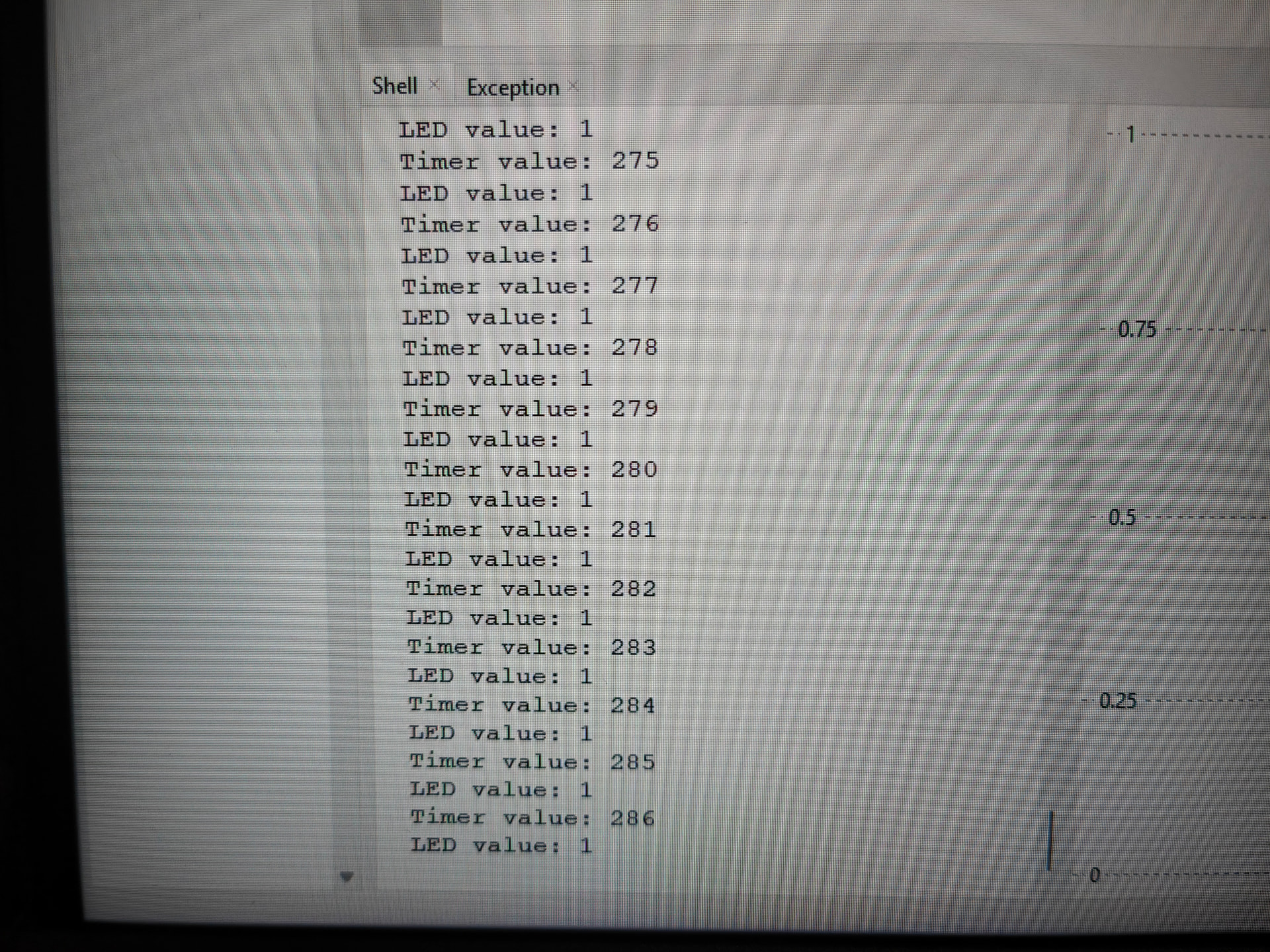
I recently bought a RP Pico starter kits (using PICO 2WH) and I’m up to 2.4 in the courses page.I’ve copied the code exactly, but when playing it the led.value() remains in a locked on (1) state even :
without pressing the button
removing the button from the circuit
removing the wiring for the LED as well (the timer counter still increases)
removing every wire from the pico / pico is only connected to the USB for power.
rearranging the circuit entirely (with equivalent arrangement), testing different resistors and potentiometer.
Additionally, if i start the code with the 3v3 wire diconnected, the timer stays at 0, but as soon as I connect anything the timer starts counting again in a locked state, only stopping if and only if I remove the USB power cable.
I’ve tried experimenting with another identical raspberry Pico but got the same results as stated above.
I’m not sure why that’s triggering the Pico to think that the button is always pressed. Surely the circuit would think that it’s never being pressed instead.
But try it connecting the button to ground instead of the 3v3 rail.
Hi Jane
Would not be too sure about that
From an earlier post
There might be some confusion here. Like is the code in use AT THE MOMENT actually as earlier where ths {in 15 is internally pulled DOWN.
Has the actual voltage on pin 15 been measured as requested bu Michael. That would be the first logical step. Could solve all problems
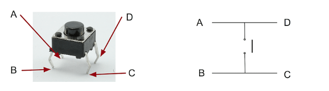
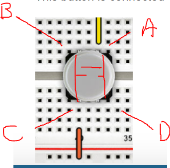
Has the actual button been checked. Some of these have both pins on one side connected together and the same for the other 2 pins. The result, if the button was inserted 90º out of position it would look like it was pressed all the time..
I would have thought that these 2 things (Voltage and button orientation) would have been the first things checked.
Cheers Bob
Just noticed you are using diagonally opposed pins on the button so it should work anyway. Probably worth checking though.
By Michael and Jane’s recommendations I’ve tested the voltage of pin 15 in comparison with both ground and the power supply 3v3. 3v3 and pin 15 do not output any voltage whatsoever, while 15 to ground does ~ -3V (inverted multimeter pin placement). Interestingly enough:
While the circuit is connected, nothing happens when I place the multimeter pins on the pico board. Then, disconnecting the 15pin, the LED was still on, but interestingly turns off when I connect the ground pin to 15pin only using the multimeter.
I have tried this with both orientations of the button ensuring diagonal wire connection, I’ve also tried different buttons, am getting the same results as the original post and this reply. here is the button I’m currently using Switch and Cap Assortment Pack | Buy in Australia | CE08583 | Core Electronics and the other buttons I used were mini push buttons (also from core electronics).
I’ve also tried grounding the button as per Jane’s recommendation but it doesn’t seem to do much as the LED remains on until I disconnect the whole circuit from the USB power supply.
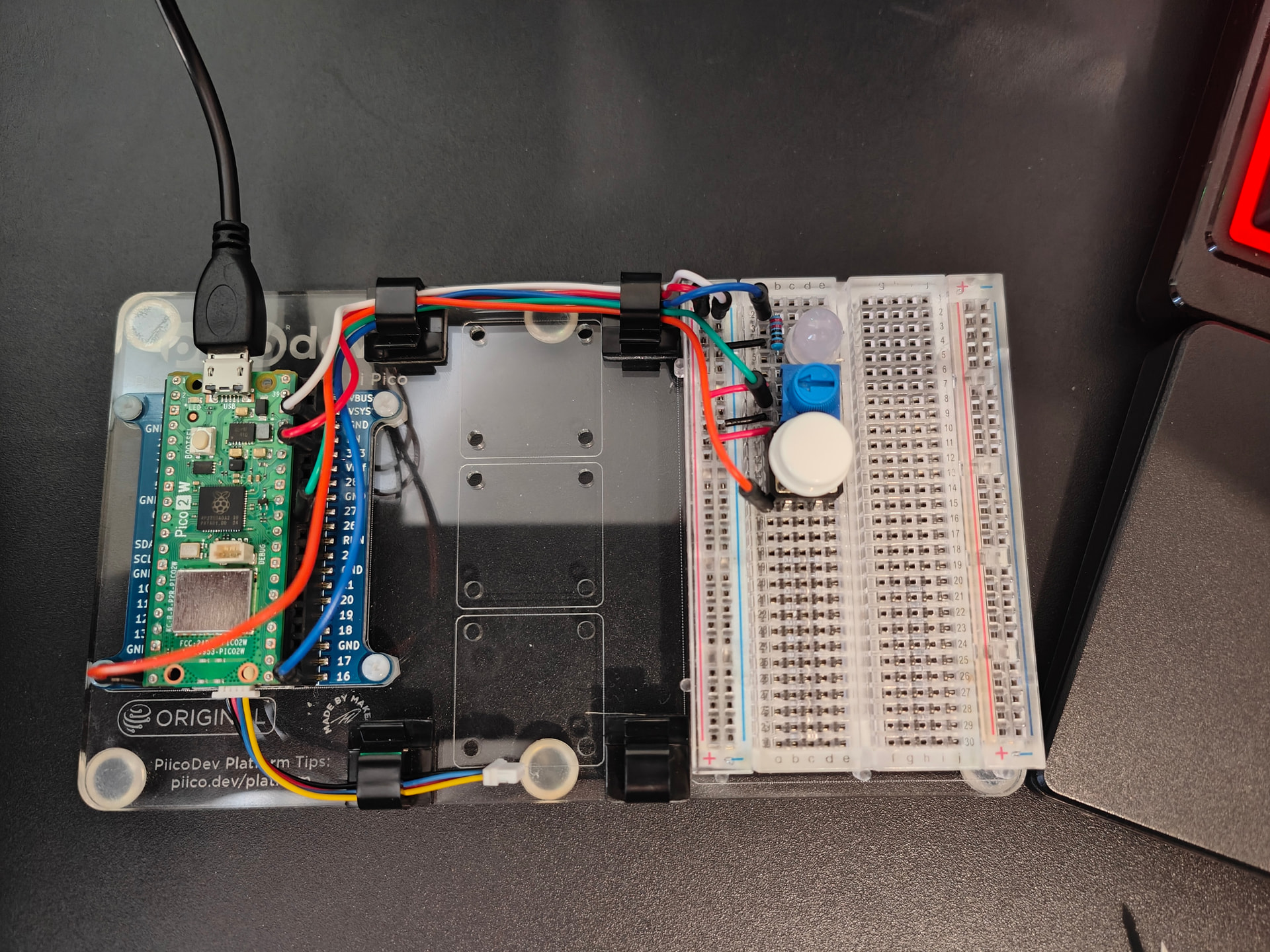
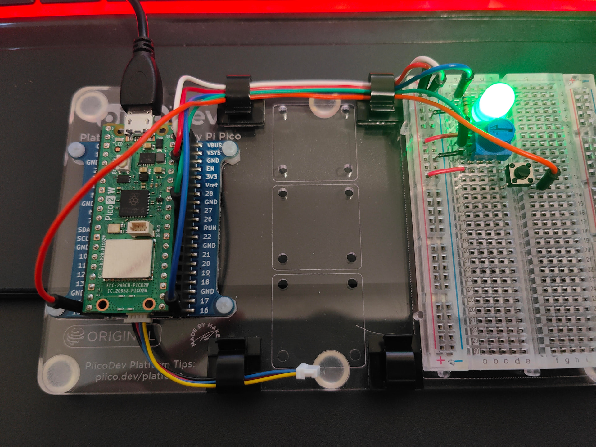
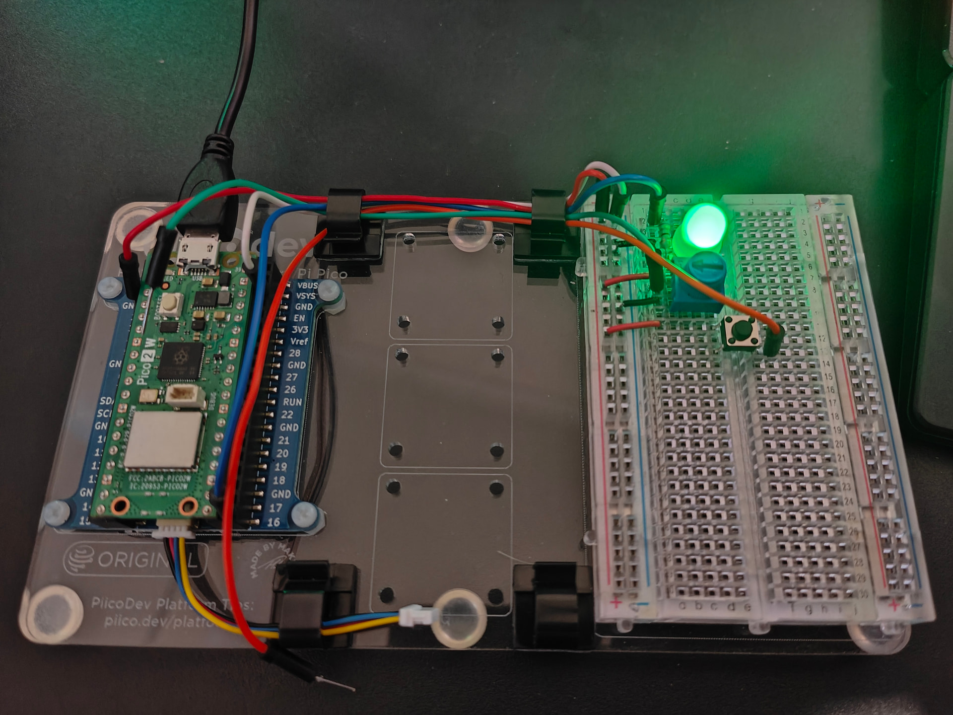
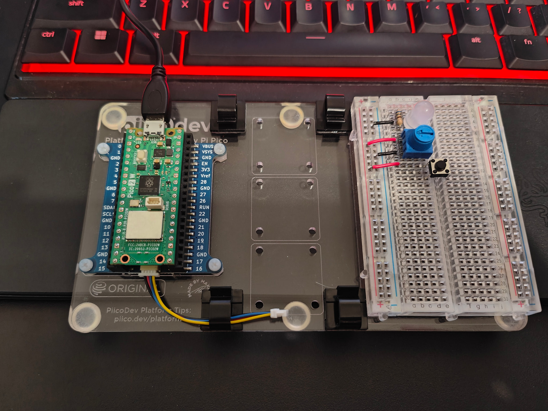
Hopefully that rambling makes sense. I would upload my video of the testing process but I don’t see an option. I’ve included a photo of the circuit arrangement but I ain’t smart enough to see the problem immediately.
Another detail: without connecting 15pin to anything, the LED latches on and off if I just use one end of the multimeter and lightly tap the 15pin. Not too sure what’s happening.
I assume when you tested the voltage at pin 15 that the full circuit (as per the above posts) was still connected.
pin 15 in comparison with ground : - -3V
This would make sense IF the wire to pin 15 was supplying power via the button.
pin 15 in comparison with 3v3. : no output any voltage whatsoever
This is constant with the above.
Can you re-run that test with the wire between the button and pin 15 disconnected.
i.e. Measure the voltage between ground and the “disconnected” pin 15
then measure the voltage between ground and the wire that would have gone to pin 15.
If the pico is doing what the code says, the pin 15 (no wires connected) should be 0V, and based on your challenge, the wire that would have gone to 15 via the button should be about 3.3V.
If that is true, then as per bobs post, buzz out the button to see what’s connected to what.
Remove the button from the circuit.
draw a picture and lable the pins so you can keep track of things
with the multimeter in continuity mode (touch the two probes together, they should buzz.
then test what is connected to what
Round 1 - Button NOT pressed
e.g. If you labled the pins 1,2,3 and 4 then we need to test the continuity between.
1 - 2
1 - 3
1 - 4
2 - 3
2 - 4
3 - 4
Round 2 - Same as above but with the Button pressed
When this is happening where is the other multimeter lead connected.
The multimeter (if it is a DMM) has an internal resistance of 10MΩ. If probing high resistance circuits this resistance will have an influence.
Cheers Bob
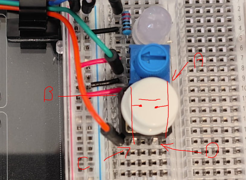
Assuming your last photo is the actual wiring, then Im going with @Robert93820 in that the switch is 90Deg out this a permanent “on” (a buzz out as in my last post will prove it).
I found a pin out that MAY be the same as your button
Hi Michael
If wired like the earlier image the switch would work no matter which way the switch was mounted.
This later image definitely depends on switch orientation as 2 of the switch pins would be shorted by the breadboard connections.. I don’t know why he has mounted it this way.
There again the switch needs checking as some are actually change over. ie; one pair of pins made with the switch up and the other pair of pins made with the switch pressed.
Just which type has been used.
I think Jaron could have more than one problem here. See seems to be trying to fix everything at once instead of getting the problems sorted progressively. A recipe for disaster and usually finishes up with band aids all over the place and presto !!! Something might work. Fixed it ?? I don’t think so. At the end of the day 2 or more wrongs never do make a right.Just looks that way for a while. A bit of a trap that a few people seem to get into and finish up in a hole too deep to get out of.
Cheers Bob
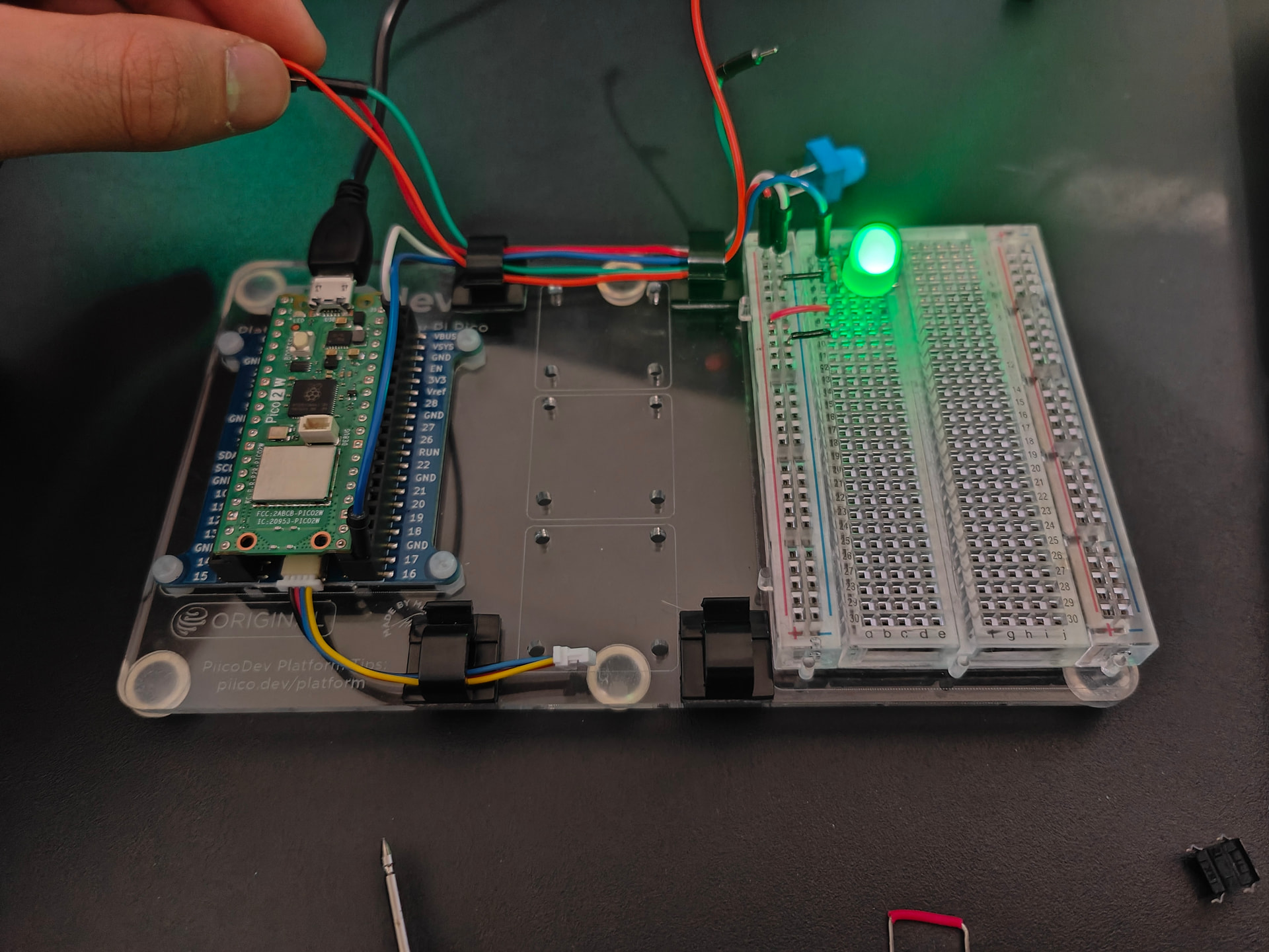
Replaced the button and tried diagonal arrangement across the breadboard. The original orientation was causing the circuit to connect regardless of button state. However:
Connecting USB power does nothing as normal. Clicking the button then turns on LED and does not turn off unless USB power is disconnected. Disconnecting pin 15, 26, and 3v3 does nothing. Disconnecting 16 and ground turns off the LED but turns back on when reconnected.
Disconnecting all but pin 16, ground. I believe for some reason the circuit thinks that button.value is constantly 1 even though literally nothing is connected to pin 15. In this state, when I use the multimeter to measure the voltage between ground and 15, the LED sometimes turns off (no voltage reading), sometimes turns on (-2V reading this time). If the LED is turned off this way, connecting the MM pins to 3v3 and 15 can both turn the LED on and off. I no longer know what’s happening.
Disconnecting potentiometer does nothing to the stated above.
“Hello there circuit. Can you tell me what pin number 15 is connected to?”
”Sure thing. Nothing!”
”Ok cool. So if I check you, your button value is going to be zero ri-”
”No.”
Hi Jaron
I apologise. It is there if one looks closely. It is (almost) pretty invisible in those photos. It looked as if they black wire connected directly to the LED.
Sometimes with these photos it is very difficult to determine exactly where a wire is connected. Particularly when the wire has a pin crimped to it with that black housing. When they are plugged in to the female headers in a Pi or similar the camera angle causes some parallax error and sometimes you can’t decide exactly which point the pin is plugged into.
Also you have several red wires which all look the same.
If you care to look at your pic in post 5 you will see at top left that they both under the white wire. Now it is difficult to decide after that which red wire is which without really going off to study up the Pico pin outs and decide from that. Also on the breadboard it is not immediately obvious that the 2 horizontal wires are actually links to the positive bus. Also it is impossible from the pic to see exactly which pins the White, Red and green wire connect to on the Pico.
Cheers Bob
I have not spent too much time looking for the offical document, but it seems that the Pico 2W has a fault with pull down resistors.
You've come across the infamous Errata 9 bug; in short, built-in pull-downs don't work correctly on RP2350.
Assuming what you are seeing is the bug, you have 2 options.
Rewire the circuit and adjust the code to use the pull up.
i.e. pin 15 to button to ground. Set internal pin as input with a pull up. Now “1” will be no button pressed and 0 will be pressed.
put in a 10K or higher value resister between pin 15 and ground and disable the internal pull down (i.e. no pull up or down)
i.e. Pin 15 → Button → 3.3v (as is)
Pin 15 → 10K or bigger → ground.
Edit:
Alternatively an 8.2kohm or lower can be installed as an external pull-down
Key Note: the external pull down may need to be stronger