Hi This is my first real post to the forum and will be my first build of a real product.
I am making a DCC (Digital Command Control) Master Station for model trains using the PICO version 1 chip and PIO & MicroPython. The Pico will drive 2 outputs Complementary Pair using small pulses ie 58us for Bit = 1 and 100us for Bit = 0, with interpacket timeout of 5ms.
Software of both the DCC Master Station & DCC Sniffer/Analyser is successfully running to a Digital Storage Oscilloscope - 2 channels at 100MHz to confirm voltage and timing of pulses.
The pico will drive 3A 4V-16V 2 Channel DC Motor Driver - SKU: CE08406 Brand: The Pi Hut
3A 4V-16V 2 Channel DC Motor Driver | Buy in Australia | CE08406 | Core Electronics for $18.70
The DCC to the track is Alternating Voltage swapping the Input Power supply rails in tandem, with the Zero DC Voltage.
Datasheet Extract on 3A 4V-16V 2 Channel DC Motor Driver - SKU: CE08406 Brand: The Pi Hut:
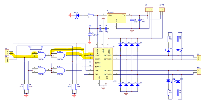
Schematic of the L298N Chip, ie 2A Dual Motor Controller SKU: DRI0002 Brand: DFRobot
Prototyping:
This other brand which is only 2Amps, does the inversion on the the board
QUESTIONS:
-
Has anyone had experience with this motor controller driven by fast pulses ?
-
for building up the real prototype breadboard (ie soldered), what do i use for the solid wire to form the various tracks etc
-
Prototyping boards: ie Makerverse Perfboard 1160 Tie Points | Buy in Australia | CE07928 | Core Electronics
Are they double sided for soldering ?
4a) Can anyone recommend any firm for making small runs of print circuit boards < 6 ?
4b) What software do i use to design the boards ?
- The PICODev Base Boards come with 2 types of nylon nuts.screws standoffs ie 2.0mm ? 2.5mm & 3mm
a) Can anyone tell me what the smaller size is ?
b) Does Core Electronics stock these if so can someone give me the link to these items in the catalog.
Note:
Thanks,
Geoff.
1 Like
Hi Geoff
If you are working off that truth table and the schematic provided it can’t happen.
The braking situation where both inputs are LOW or HIGH cannot happen due to the input arrangement. The inputs must be always opposite. They are connected to the input and output of a NAND gate configured as an inverting buffer.
I have not looked closely at the L298 for a long time but I think this arrangement of applying the PWM to the enable pin means you cannot “creep” the motor very slowly from standstill. The reason is because you never get the flywheel diodes directly across the motor, one connects via the power supply (I think from memory).
You can but try but if I am correct and you can’t creep I did post comments re this a few years ago and offered to post oscilloscope pics showing the problem but no one was interested so I promptly forgot it and kept the info to myself.
One of the other chips I was playing with at the time when this type of PWM drive and H bridges were becoming popular actually went HIGH Z outputs during the OFF period so there was no effective flyback diodes at all and the whole thing went up in smoke. That particular project really needed to creep the motor from standstill and I finished doing the reversing with a relay.
Cheers Bob
1 Like
The circuit shown does not allow the two bridge inputs to be at the same level, but the enable input is quite separate. It will work just fine with speed/direction control. But it refers to the DR10002 driver, and the truth table the manufacturer provides for that driver is not the one listed above.
| E |
M |
RUN |
| LOW |
LOW/HIGH |
STOP |
| HIGH |
HIGH |
Back Direction |
| HIGH |
LOW |
Forward direction |
| PWM |
LOW/HIGH |
Speed |
which matches the schematic for that board and includes the condition where both inputs are at the same level. Without knowing the schematic for CE08406 it is not possible to say whether or not the truth table provided is correct, but there is no reason that it couldn’t include different or additional circuitry to match those conditions. The problem is that there is no indication of how the PWM is used to control speed. The library code does it like this (paraphrased):
            if (speed >= 0)
            {
                  analogWrite(_pin1, speed);
                  digitalWrite(_pin2, LOW);
            }
            else
            {
                  analogWrite(_pin1, -speed);
                  digitalWrite(_pin2, HIGH);
            }
which suggests the two modules operate in the same way (where E is input A and M is input B).
1 Like
Hi Jeff
Agree.
But what I pointed out was that all the drivers I tried (not all available obviously) that used the technique of selecting IN 1 and IN 2 for direction and applied PWM to the Enable pin would not start up slowly from standstill. When the PWM duty cycle is increased the motor would start with a rush at about 25% full speed then it could be slowed.
I just thought that Geoff might want to start his trains very slowly at different stages and should be aware of what could happen.
I did start a thread about this a few years ago now and offered to go into detail with oscilloscope pics but it generated no interest at all so I figured everybody knew about it and I dropped it.
This came up a few days ago and I offered an abridged description so I will not go into it again. The thread appears here
DC Motor datasheet
11 days ago.
I describe what happens in the last post and the lead up to this is really the whole thread.
Cheers Bob
1 Like


