Need help with extremely complicated ws2812b strips project!

Ok, this is something I kinda don’t like doing and should ONLY be taken as is an example.
In the example, I am in no way recommending any Parts.

The objective is to ensure power return paths are via the correct rated wires and that devices providing signals/data normal need a common ground. Connecting grounds is not connecting the power supplies, rather ensure all components see the same ground reference, so that they can read the correct signal levels.

This is very rough and ready and I may have missed something… but assuming you have 3 controllers, 3 led segments and 3 power supplies, and assuming the controllers are linked to a “master” for a sync/start pulse.

Something like this…
(I am more then happy for others to chime in here as I may have missed something or get something not 100% due to rushing it…)

Again, this is just an indication.

I will also add that things like DC-DC converters can add power noise that may need filtering; but I feel we are trying to cover all potential issues rather that fix a specific issue.

With electrics, you can end up with issues for lots of reasons, but you work the issue to fix it. On paper something can be perfect but in the real world something cases an issue.

Edit:
I would also like to stress that I would develop all the code myself for these projects and as such can control everything the way I want. e.g. I am running 1024 WS2812B leds off a 500watt power supply, with a power injection point every 256 leds (direct back to the power supply) I am also clocking out all the data as one long 1024 Pixel display using RMT on the ESP32.
The ESP32 is running of a USB Port as I am pushing firmware to it, but there is a single ground connection to the ground with the data wire.

Hi Darkmaster
I just pointed out a couple of things above that seem to be overlooked.
What I said above about 3.7V to 5V conversion in a power bank is FACT.
Also a “power bank” is designed to be a secondary or emergency charging system NOT a “power supply” That is also FACT.
Also

And

May not always go together. That is also FACT.
And most of it is PHYSICS, pretty difficult to change.
You may make of this what you like.
Cheers Bob

@Michael99645 Its seems on the diagram thats exactly what I proposed to @Jeff105671 earlier, but I’m taking it that each LED strip, Microcontroller, power and wiring/cables are each its own segment, meaning that at least 8 of those separate segments are needed to build such an arrangement.

And it’s not all on paper. It’s proven on video and in rl cases. My provided link should fill in more details in case you’ve forgotten.

I don’t know where you read that, but ground and power connection for each strip is the required setup, regardless of how many power sources you have. For long strips multiple ground and power connections might be required.

If you are contemplating a USB ‘keep alive’ then you are looking at the wrong sort of power supply. You don’t want a battery that needs a “keep alive” - you want one that you simply turn off and on. I’m not sure how you have calculated your power requirements without knowing the length of your strips - that’s a critical part of the calculation.

Low power state refers to how much power it uses use when it’s are not doing anything. It’s not relevant to your application because you will simply turn the power off when it’s not doing anything. But the heat issue is not related to the MCU - it’s related to the gauge wire you need to use for your connections to ensure that power is not lost in heating up undersized wiring.

That’s the diagram you posted, modified as I suggested because you can’t power the LEDS from the MCU. If that’s not suitable for some reason, you should describe what the issue is.

No. The temperature of the LEDs depends on how you control them - hard on all the time is maximum temperature, dimmer or only on some of the time is cooler. Running more than one power connection to the LED strips can allow you to use thinner cabling without running a risk of excessive voltage drop and possibly overheated wires or connectors.

A BLE connection (or WiFi) will enable you to control the MCU from a remote controller. It will not change the wiring configuration you need. It only changes whether the control information comes from software in the MCU, or instructions transmitted over wireless to the MCU.

Hi Robert,

Whether or not one chooses compact or portable, or opted for results instead, at least someone out there pulled it off. It’s shown to work, so there must be a workaround for such a result. Instead of trying to analyse those videos if you are still doubtful, you’re trying to say like others do, that its impossible.

And thats a FACT.

Where did I say that???
I’m outta here
Cheers Bob

I’m trying to @Robert93820 but you seem to think this project is impossible (much like @Michael99645 believes it to be),

Im not sure where you are getting that from ?

I think you may be confusing tips and things to avoid as being impossible. But its not our job to design the project for you; we are here to help ensure it can work.

If you where to test and experement with this first you would see what we are talking about to some extent; but you seem to be trying to go direct to a working product; this without the experience may or may not work as you expect.

Since this is a “suite” if things get hot they can catch on fire and it becomes very easy to hurt someone.

And it’s not all on paper. It’s proven on video and in rl cases. My provided link should fill in more details in case you’ve forgotten.

Yes and No. If the video has outlined all the components, power supplies, wire sizes and code to run, then OK, but then we would not be here talking about it.
Just because someone has done it, does not mean running the wrong components.

I am very sure it can be done; I have done bigger projects on that with these LEDs… so I am 100% it can be done.

My big concern is not that its impossible, rather that you steam to be struggling with some basic things that, if you get wrong, at the least will just be a failed project, but at the worst can hurt someone. How would you feel if the person put this suit on, got on stage and the whole thing bust into flames… this can be the result of it not being done write.

I am basing this on two things.

  1. You repeat that you are a beginner (which is fine, but that means you need to learn and understand).

  2. You keep wanting to skip over the impact of high current needs and don’t seem to get it that small wires will get hot and burn with these currents… so you need to mitigate that… either by reducing the current OR increasing the size of the wires/parts.

This is why I think you need to learn more about how things work BEFORE you attempt to build this. It will help you understand things.

I said way back at the start, this needs to be done in a safe way.

Yes. You have taken on a very complex task. But it doesn’t necessarily mean 8 separate power supplies or 8 separate MCU. At a minimum you could do 1 of each (which would be a large battery, powerful MCU (like a Pico) and a lot of wiring), or a maximum 8 of each (for smaller batteries, simpler MCU (like a ESP32C3), simpler wiring but a lot of repetition). Two of each is a possibility, like your diagram. One advantage of 8 of each is that you build and test each separately, so you confirm everything is working as you go.

My inclination would be two for the top (one shoulder, one sides) because they would probably have to be sewn into the middle of the back and therefore should be as small as possible. Then one for the pants because concealing a larger battery in the waistband would be easy. But that’s a decision you would make after you have considered exactly what’s involved in putting each one together.

I totally agree with you on doing this but keeping to the safer side. That’s why I’m struggling to figure out wire types best suited for this project, how they can be connect (as one centralised arrangement of components or each individual system for each section of the outfit) and function without compromising its physical state and functionality. I poured for answers from reddit, arduino forums, youtube, other tutorial and handy tips sources, etc. but all providing way too many different answers and solutions which only confused this whole trajectory.

To save me from scrimming thru endless hypothesises and theories it’s better if I provided the type of components I specifically picked that seemed to deliver similar results based on several minutes of video analysing and comparing but I feel that it would be much better if I just get referred directly to specifically the components (branding and specs as an example) and how many I would need to obtained and where to buy such and such.

Since combining and connecting all to the same power source and splitter cables would’ve help much at all (or at least compromised the components), I’ve taken advice here and there and am starting to fill in the details and minimised as much potential risks as possible (as said with overheating and wire strain as a few). I just needed a few (or some) more directions as to how to actually come up with the right combination of components, non-code programming functions that work as intended, and keeping the components portable and compact as possible. I would only go around in circles if I’m forced to figure out the entirety of the process if someone else’s suggestions contradicts other experts here and result in massive brainstorming that adds more to the confusion in the process. I can provide the type, version and link as to go thru which is less of a hassle to modify to meet safety standards, as well as suggest changes such as reducing brightness, opting for other addressable RGBW LED strips that have the same diode size as a 5050 SMD but not necessarily WS2812B strips which means getting less- specs demanding components.

All in all, a huge manual compiled will save me from having to ask excessively in case of accidental testing that compromises any components and prioritising safety as well. Hope I’ve gone as far as suggesting what help I would much rather need as to make this less time-consuming and headache-free.

Lets do some rough math (I may have missed the number of LEDs somewhere, so that’s on me if I have)
Number of LEDs : 300
Assuming a max current of 60mA per led (may be 40 or 50 as actual exact numbers seems hard to come from, but for safety we go over not under).
300 * 0.06A = 18 Amps
Lets assume all the power is running from the power supply to the first LED (and some other assumptions about the copper used in the wire etc)
Then to push 18A over 1 wire over 1 Meter in distance, then the wire size should be a minimum of 4.928 mm2 (which will be about 2.5mm wire diameter (i.e. just the wire) so the insulation would be added to that. Lets go with about 1mm insulation thickness and we now have a physical thickness total of 5.5mm diameter.

Now when we see that, it MAY be ok for the application, by may be too thick to be practical. e.g. to connect to JST connectors or solder etc.

So what we can then do, is say have two runs (lets assume left and right hand side of the suit). I am assuming that both are a mirror of each other.
So now we only need to support 1/2 the current on each wire (going to each side); but that still needs 2.46mm2 (1.77 mm dia) so adding 1mm insulation, we have a wire now of 3.77mm and not 5.5mm
Now if we split into 4 sections (of equal or about the same number of leds) then (without doing the each one by one, assuming the current is 1/4 of the original)
We now only need 4 runs of 1.232 mm2 (1.25mm Dia)
so with insulation of 1mm about 3.25mm.

Assuming the power supply can deliver the full 18 Amps (for this example), then you would run all 4 power (Pos and ground) back to the one power supply. But this will depend on the power supply. e.g. One of my 20Amp/hr power supplies will only deliver a peek current of 3 Amps out the 5V usb port, so that power brick wont work.
BUT to get the current down to < 3Amps, a target would be abut 2Amps if max is 3 (some buffer room and losses). then you would need 9 Of them, so that’s way too many for this project.

So assuming we need the 18Amps @5 V (for 300 LEDs) then now we need to find suitable power supplies that can deliver 18Amps at 5V, or 2 * 9 Amps (assume you can split the power needs at 50%).

So… a bit of home work to see what power supplies you can find that are portable, and can output the needed power.

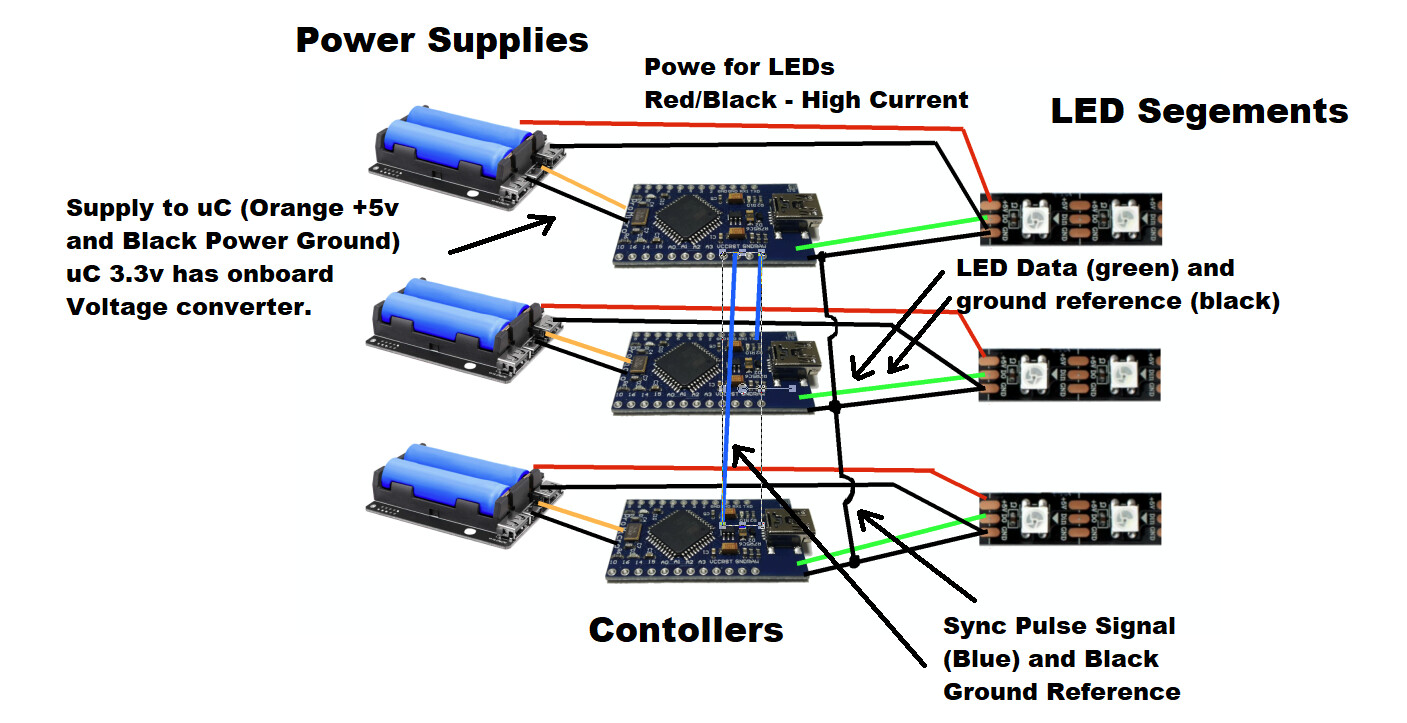
So if you can find 1 big power supply and use that as 5V via a power regulator to 3.3V (most uC have on onboard 3.3v regulator) then all the grounds are at the same reference, and things look simpler.
So we are looking at design considerations. Some of these will be dictated by the devices/firmware etc that is used. you can run over 1000 LEDs off the one controller pin (assuming you can clock out fast enough; which an ESP32 can)
So with a single power supply (if it can be found), you can have one big string with one uC so no sync needed.
Pro: Simpler design
Con: Bigger single power needs
A single LED failure will stop ever led after it.
May be harder to code to get the effects you want with chosen software/firmware.
(Like I said, I would just write the code from scratch, then I dont have any limits from ready made devices); But since I dont tend to use ready made, I cant comment on what may or may not work.

Now: If we need 2 power supplies, then we need to have the V go to two separate strings. But that is just the Power +V. we can still connect the gounds for a common ground, then have one big string, just first 1/2 from power supply 1, second 1/2 from power supply 2.
Same as above with controller/software.

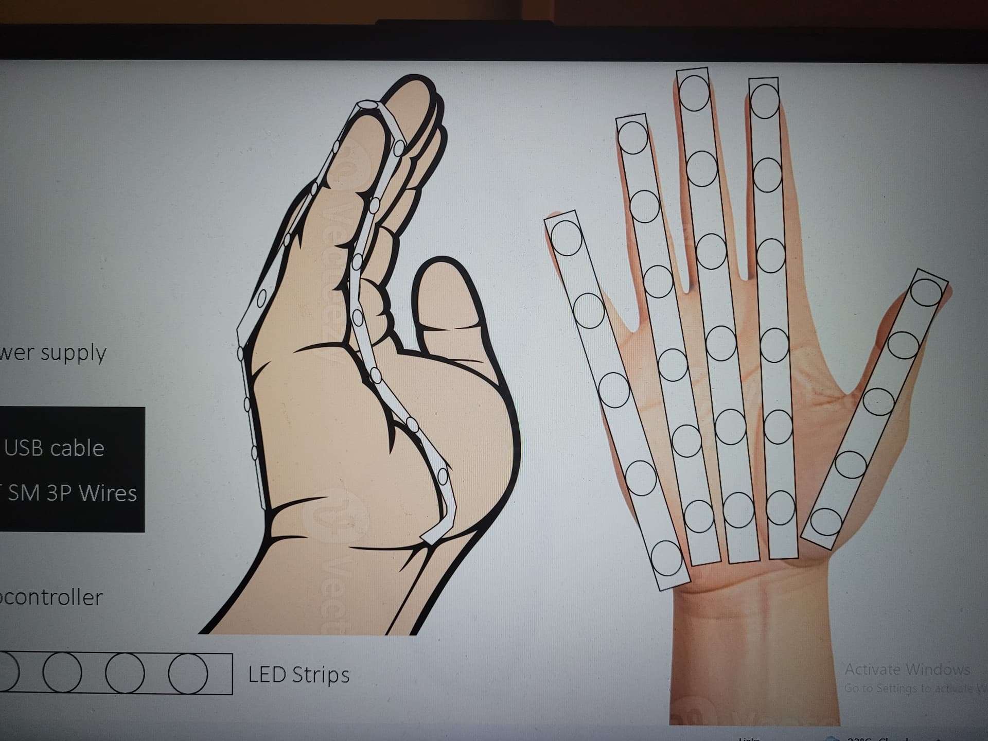
So, the key take away here is you start with knowing 100% you many leds and how they are broken up. I did see your image, but was not sure on the actual number of LEDs.
You then work out the power needs (worst case) add a buffer to that, then find what power supply options you have.
Once you know the how many supplies you need (1,2 3 …)
then you can work out the best way to wire those into the LED strips. As per my example above you need to define the max wire + insulation thickness that you can work with (i.e. the connectors/solder pad size etc.) This will dictate how many power injection points. But with 300 LEDs, I would have a min. of 2, but considering every point at which the LED strip is cut can be a power injection point, that will make it easy to work out. e.g. If you had 3 Segments per side Top (Solder/Arm), Upper Leg and Lower Leg, then you have got 3 easy power injection points per side… so a total of 6 back to the power supply.

Does that make sense ?
Firm up the exact number of LEDs, where the are and where the break points are.

Maybe. The challenge with that statement is the answer will be it depends. The assumption the vendors work under is the person designing the system knows what they are doing and will design a system that meets “that projects” needs.
e.g. In my 1024 LED project, its easy, I just got 1 big enough 240V to 5V power supply and can bolt heat sinks to the back of the LEDs, so easy. But in your case, heat sinks wont really work as they will be bulky and running a 240 Extension lead is just not going to work :slight_smile:
So this means the actual solution is different; and will be driven by your constraints; and no one knows your constraints until you design your project.

Anyone that has be doing this long enough and/or complete training in some form of basic electronics would understand what their project needs; or at the very least think they know, build it, then have an issue that they then resolve… at which point will have learnt what the need to know for next time.

The assumption that their is a design guide does not really work.

You won’t get that without a lot more detail of your requirements, some of which you won’t know until you start, and that might mean changing things as you go. For instance, you have said you are going to use ‘4x WS2812B (SMD 5050) strips 144LEDs/m IP67’ but you haven’t indicated what length each of the strips is, or the total. It’s the length of that strip that determines the number of LEDS and the power requirement. You haven’t indicated how long it needs to run for - 5m has been mentioned. Is that the requirement? You haven’t indicated what the outfit is, so there’s no clue as to how much room there is for the equipment. But, just in case it’s useful, I’ll answer your question.

Power:
Dual 18650 battery holder with 5V 2A (LEDs) and 3.3V 1A (MCU) output.
I thought Core had these but I can’t find them now.
18650 batteries
Hookup wire OK for starting, while you determine what the loads will be and what gauge will be required.

MCU
ESp323C. There are many variants that are suitable. This one requires a type C USB cable for programming.

Breadboard
Breadboard jumpers

LED Strip Keep it simple to start with.
Level Converter May be required if the LEDs do not work reliably with a 3.3V control

Note that you will also need a soldering station, solder etc. This will enable you to build a prototype of one segment and create example patterns for testing. The results from that prototype can be used to determine how the design needs to proceed.

Sorry for not being specific on the components, but I’ll list them here with more info and detail:

WS2812B (5050 SMD) LED strip: I presumed its going to be 1m long, with 144 LED diodes per meter I presume. Here’s the lengths I needed (according to measurements): 1m length for the jacket section (from tip of sleeve to base of jacket)
and 92cm for the pants side strips (both legs outer-side)
I’ll be certain that the shoulder strips be 50cm in-between range. And that the inner-side strips be 82 or little more or less within range.
Might also consider reducing brightness level to somewhere between 75%-80%? Would that affect the heat levels to certain extent?
Also considering the input voltage is DC 5V, would also mean 5V is the minimum and not the 3.3V, but I could be wrong.

Link: aliexpress.com/item/2036819167.html

Microcontroller: For compact size-related factors would the Seeed Studio XIAO ESP32-C3 fit that description? Also would need a GUI interface (or a way for GUI graphics to be converted into code for either Arduino or Pi) that lets me select animation sequences and preset them into a programmed timeline that automatically runs upon remote activation via app/bluetooth/control. I’ll also take into consideration your recommended ESP32 module on the provided link but also the issue would be where to solder each wire between the module and the LED strips. And also as an extra note: anything that works with LEDFx and WLED, coding will only be a burdensome hurdle to learn from scratch.

Link: Seeed Studio XIAO ESP32-C3 | Buy in Australia | SS113991054 | Core Electronics

Power source: If battery packs like the suggested dual18650 batteries + holder can rival that with powerbanks of 20,000 mAh capacity and 5V input/output and not switch off entirely when voltage drops are detected (a member here mentioned that as a downside as some animation sequences remain blank/black for a short while/brief moment in-between animation transitions and light-up sequences. The video shows tiny moments when there are brief instances of pause before the LEDs lit up again so if you watch the video in its entirety (the top video) you will see what I mean. Powerbanks were the 1st to come to mind because it was suggested by some other people in a discord I am part of to use to power the LEDs who worked on LEDs for wearables and cosplay props/outfits and that they are compact as one object and more streamlined and less bulky, but I’d like to hear how you can point out many functionality benefits battery packs and holders have over powerbanks of 20,000 mAh and with DC 5V inputs/outputs.

Wires: since the LED strips mentioned and focused on have some sort of 3 Pin connector on both ends for data input and output, maybe wires that correspond to that layout and design could ensure compatibility? If JMT SM 3-pin wires/cables are not ideal for this case, and there still needs to be connections to power the LED strips and connections to program the LEDs via the microcontrollers, what other wires/cables can be more suitable to balance the 2 requirements?

Lastly but not least: A diagram of the setup to keep each component not tangled up in some mess or the least complicated would do, it’s about as much more in-depth as I can go, let me know what your thoughts are and any more advice that proves useful and contributes to delivering as close to what the video shows.

Thanks for the tremendous amount of maths, which I alone could not have come up with. But here are more info to give you a better picture:

The lengths of the strips for each section as follows:

Jacket section: 1m for a strip that measures from the tip of the sleeve to the base of the jacket.

Pants section: 92cm for each side strip.(running from the base of the waist to the tip of the pants sleeve)

The WS2812B LED Strips (5050 SMD) have 144 LEDs per metre, so when purchased they come as 1 metre default. (Take those measurements I provided and try to ‘math’ them up to scale to see how much LEDs are there in total) they also have a IP rating of 67.

Link: aliexpress.com/item/2036819167.html

Note: I still have not come up with measurements for the glove as I have been preoccupied working on the specs, measurements and arrangements in regards to the jacket and pants. But I have made my best bet to use 1 metre of WS2812B LED strip with 60 LEDs per metre and an IP rating of 65.
Each finger on the hand would have 1 strip cut/trimmed to the size that wraps around each finger and aligned vertically from back of the hand to the base of the palm. How to power those 5 strips, connect them to a microcontroller that fits in the area covered by the glove and powered by the most compact (size is a bonus) power source is something that would take me ages to come up with, if my mind can handle all the headaches to come up with an arranged setup that doesn’t compromise the functionality.

As for the wires, the LED strips come coiled up and have 3-pin connectors on both ends of the strips. I wonder if it has something to do with what wires are cross-compatible to connect for power and data input/output.

Durability and flexibility comes to a hurdle when it comes to the legs section. Where the kneecap is, theres bound to be a bend/curved arc and that might be a problem for the freedom of movement for the LED strips overall structure. A dividend/break off in the area of the kneecap level connected by 3-Pin connector wires as 2 separate strips might grant that flexibility yet not compromise the functionality?

Then power source. The LED strips description mentioned the input voltage as DC 5V, and the strips in question (144 LEDs per metre) have a total power of 43.2 watts per metre, which converted to mAh is 8640 mAh per strip. Size, in terms of bulkiness/slim build of the power source and how in blends into the structure of the clothing comes to mind. Also it needs to not shut down whenever a voltage drop is detected especially if there are brief moments where the animation isn’t running, static or briefly in black mode (but you get the idea).

Finally, the microcontrollers. There are many tabs to solder on to, especially with the Seeed Studio XIAO ESP32-C3, and where to solder the connections to the LED strips and perhaps a non-powerbank compact portable power supply (i.e battery packs) is the most confusing part.

If you need any more details or info I have not yet provided, hit me up and I’ll give more depending what I already know and am aware of.

That matches the list I provided above, so you can go with that. All your other concerns will be addressed when you make that prototype up and start testing. I would not recommend using connectors - start with the prototyping board and then solder everything together when it’s working - it will be sewn into the clothing and the connectors will just show as lumps.

Connecting the MCU is trivial - 3.3V, GND and 1 GPIO. For prototyping you will solder the LED strips at the ends.

I would suggest about an hour to put all that together. Then you can install your software (such as LEDFx and WLED), create a sample sequence and run it. That will answer all your other questions - how long does it run for with that power? does it drop out? how flexible are the strips? do they get too hot? does the software support the required effects? Everything you are asking will be answered in the testing of that prototype.

As I mentioned before, an MCU has many contact tabs. The question is, do I simply use same wirings as the JMT SM 3-pin types but without the connectors or do I use just generic copper wires with the positive and negative connections? And when you mentioned soldering the LED strips at the ends, does it meant that one end of the LED strip is soldering to the MCU, while the other end is soldered to something else?

Use the jumper wires when breadboarding, and the generic wire that I provided the link for when soldering. This is a prototype - everything is generic and subject to change if it turns out to be unsuitable. You can connect power and signal to either end or anywhere in the middle - it’s all the same bit of wire. For the prototype choose whatever is easiest (which is probably the supplied leads with the connector cut off).

/Edit
You can connect 5v and Ground to either end, or the middle. Signal must be connected at the Data In point which will always be at one end.
Edit/

I’m still confused. For connecting each wire, they all only have the 3-color coded wires (3.3V, GND and GPIO). But it seems they need to hook up to a power source and I’m not sure if testing and altering the animation sequences while connected to say, a PC running Arduino software would power them at the same time. Also, as I mentioned, I’m not sure if one microcontroller can hook up to 2 LED strips since there are many tabs and soldering the strip’s wires to the correct tabs is something that I’m still struggling to figure out. If you noticed each microcontroller had a pin-out overview, and the numerous pins made it difficult to determine which pins to solder to, which individual wire goes from where to where, and if it has room for 2 LED strips to connect to. It’s also puzzling as to know how the microcontrollers will be powered and would the PSU provide power thru the USB/USB-C connection port/wire-soldered to a battery pack.

Edit: Apologies, I figured out for the 1st/single LED strip, not sure about the 2nd strip though, but the video I tried to get sense of isn’t providing a clear idea/picture as to its Arduino programming stage and the multiple components (assuming its for the ground connections) and ohms resistor for data spikes prevention. Please do provide a diagram pointing to the correspinding pins on the Seeed Studio XIAO ESP32-C3/Pi Pico/your recommended ESP32-C3 each single wire from 2 LED strips are supposed to be soldered to.

Link: https://m.youtube.com/watch?v=zj3sa5HV2Bg

You need to connect the MCU to 3.3V and ground, and the signal for the LED strip to a GPIO pin. If the MCU is connected to a PC by USB (which it will be while programming) then 3.3V and Ground are already done through USB and do not need additional connections. It’s only when you have completed programming and removed the PC USB that you need to provide 3.3V and ground. You will have 5V and ground from the LED power supply to the LED strip, as well as the signal from the MCU GPIO. The only thing that is not obvious is that the grounds from the two power supplies (USB and the LED power supply) must be connected together, as mentioned several times above.

There is no ‘corresponding’ pins for controlling the LED strips - it depends on what has been configured in the software. Look at the descriptions of the pins for the MCU you have selected - any GPIO will probably be OK. If there is any doubt, choose one that says ‘PWM’. If it doesn’t say which ones are ‘PWM’ then it is likely that they all are. If you need a suggestion for which one to select in your software, then post a link to the pinout diagram for your MCU.

I need your opinion on best MCU for such a project as this one. I’m trying to compare the following 3:

1.) Seeed Studio XIAO ESP32-C3
2.) Raspberry Pi Pico
3.) ESP32-C3 Mini Dev Board (With Headers)

I’ve tried to compare depending on data storage, physical size and power consumption levels. Obviously Arduino-based MCUs hold up best in terms of power consumption but not sure in terms of physical size, data speeds and storage (unsure how many MBs worth of animation sequences it can store) and which ones can easily control more than one microcontroller at the same time.

Also, the most complicated part of them all: the glove. Here are a couple of rough rendering/arrangement of the LED strips in how they will be positioned, but the most baffling bit is: how can I power 5 separate LED strips without over-bulking the glove? And given that its best to connect one MCU to a max. of 2 strips (based on your suggestion), it means its going to probably be 3 MCUs, 3 PSUs and more than 5 of the supplied lead wire types. Given that even the smallest centralized interconnected system is at least 1 PSU, 1 MCU, miminum 1 LED strip and minimal of two 3-pin wires (without the connectors), which is much more suitable for such a structure (given that the functionality is prioritised over minimal physical sizing/measures?)

Extra note: the following diagrams show the front, back and side of hand view/angles. Each LED strip will cover one finger and both sides of the portion of the hand (palm-side and back of hand) as shown in the open hand diagram, with the side view of the hand showing how each LED strip would cover each finger overall and how much space they will cover. The PSU, wires and MCU arrangement is unresolved/TBD. I’ll leave it to you to help me figure out a setup for the glove.

1 Like