Hi I’ve been having a little trouble with this project WS2812 / NeoPixel Addressable LEDs: Raspberry Pi Quickstart Guide - Tutorial Australia i can’t find the problem with it. everything is the same except that I have a different logic level converter as I don’t have the equipment to solder something. I think thats the problem as It is bigger converter (see link)
It’s a bit hard to trace your wiring from your photos - if you’ve got more colours you can choose from to colour code your wiring that’s always a big help. Sometimes when I get stuck like this, I find it’s faster to pull it all out and re-wire it than to try and find what’s misconnected.
The software side should be fairly straight forward, but have you tried applying the HDMI fix in that article?
Hey @Lewis180697 - it looks like you’re using a power adapter with a reversible plug. Can you provide a shot of where the right-angle plug goes on the end of the cable? Showing the polarity markings to see if the polarity is reversed at the power supply.
A photo of the power supply sticker is also super helpful - just to rule out other polarity / supply concerns.
Are you able to measure the supply voltage at the LED strip to confirm the polarity is correct? I’m concerned there’s a couple of places it can become reversed, ie:
Do you have a multimeter with you to check that output? Checking that the voltage and polarity of the PSU that you’ve got hooked up to those jumpers would be a good place to start.
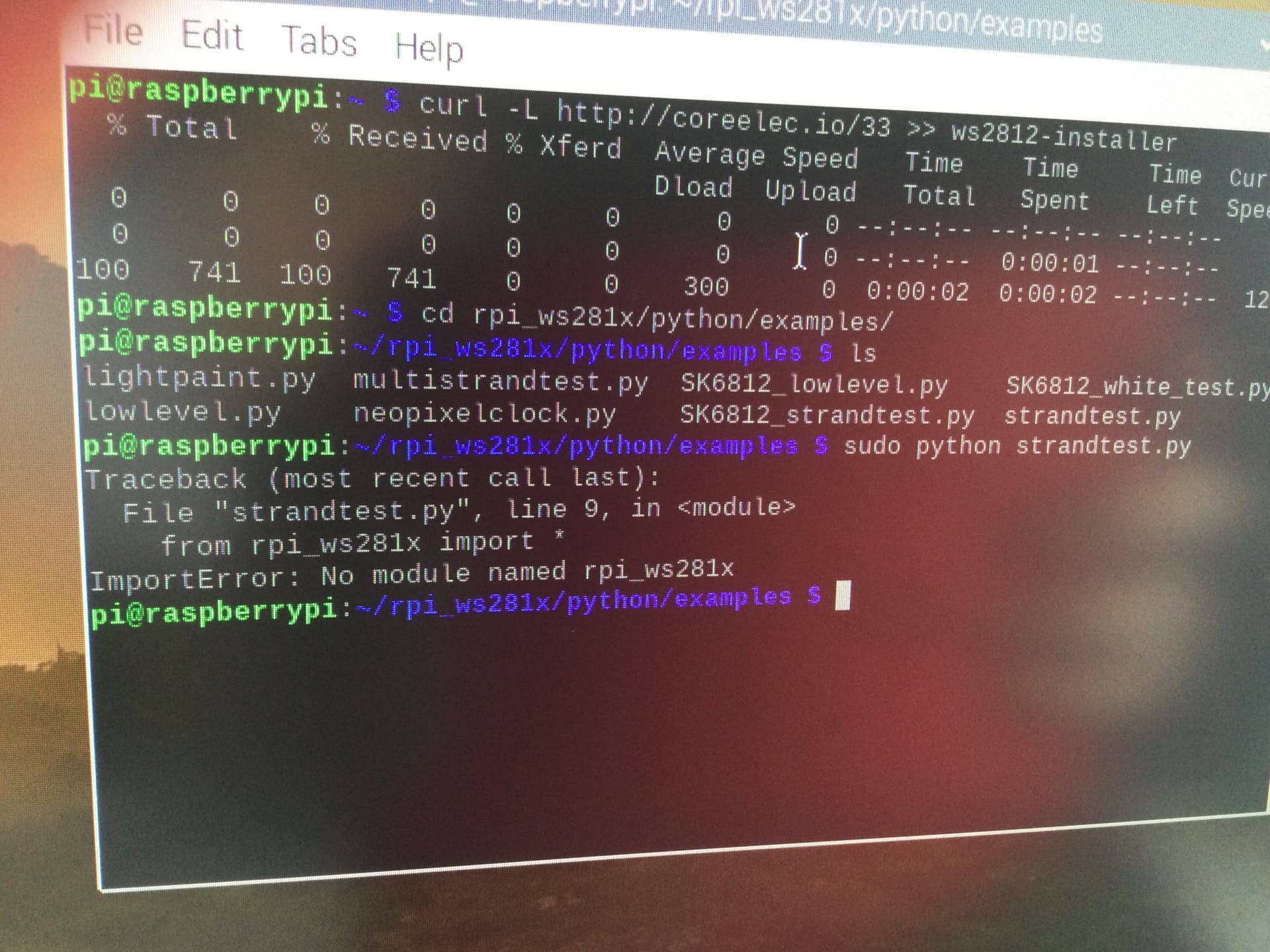
This is an issue with the code. Generally, this occurs when there’s no local installation of a library of code that is required for your program (by the way, pip is just a package manager that allows you to download code for libraries and such) that has been called for a particular library in python (in this case the missing library is rpi_ws282x)
Can you please show us the output from the command pwd if you run that from the same directory that you’re trying to run your code from? It should end in rpi_ws281x/python/examples/
As far as I know you’ll need to run the appropriate scripts first. Although can you please try running sudo curl -L http://coreelec.io/33 >> ws2812-installer again and making sure that you don’t have any issues? We’ll need to make sure that all of the modules are correctly installed before we’re able to get that running.
No it stills comes up with same error
Also a question does the led immediately turn on when you power them or do you have to run the code is so my led are just not lighting up
It says that it is already downloaded maybe it is something to do with the wiring as the led are not even turning on
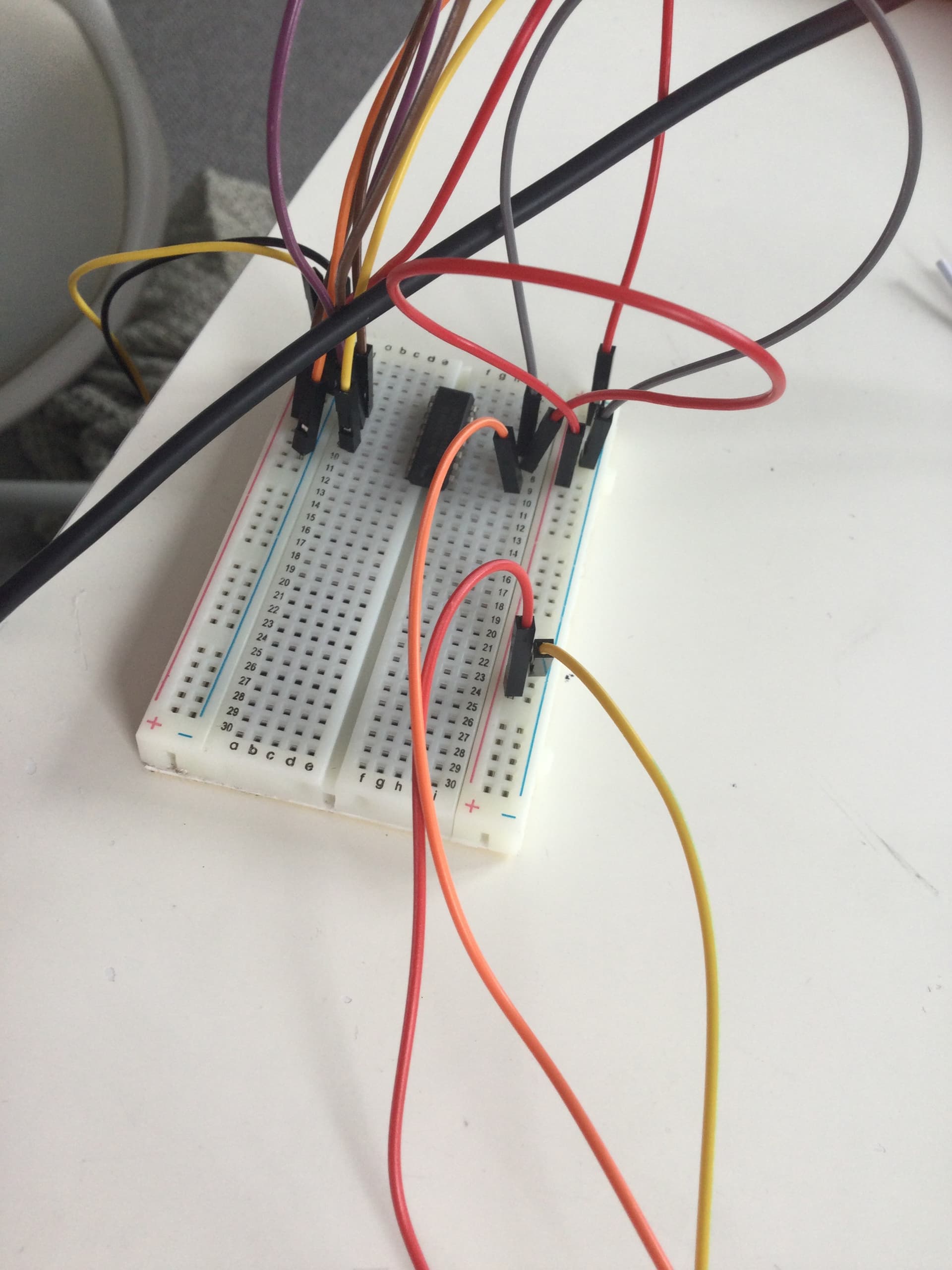
This is the wiring I have I just have a bigger logic level converter
And the wires are a bit messy as this is my first project and I’ve checked and I can’t find anything wrongimage|375x500
My raspberry Pi just started smoking and I’ve think I’ve blown it don’t know how maybe Because of the 5v and the extra 5v it blew it or maybe I wired it wrong I was just doing it how I normally doing and it just started smoking anyone and my project is due in a week is there any project like this which dont use a raspberry Pi and use the around the same maritels and stuff I already using I know it’s a lot to ask but I’m panicking here my mum is going off at me and this project counts towards my grade if someone can help me please thanks
It would help if the contributors knew what that IC is. There must be hundreds of thousands of 14 pin ICs out there.
I don’t know anything about RPi or the programming of but it would certainly help to have a multimeter to check voltages and polarities. I think that is a must when trying to do this sort ofd thing. I can’t see any reason why the set up showing the red logic level converter would not work except if there is a polarity reversal somewhere. Your last post with smoke suggests something wrong along these lines…
I have recently been playing with what I hope to be XMAS lights but using 5V Arduino (Arduino is my limit at this stage) with no need for level converter and everything seems to be working straight “out of the box” as the saying goes. BUT I have a multimeter so I can check everything before switch on. An investment of not much more than $20 on a cheap meter that will do this job anyway would be a wise move I think.
Cheers Bob
We’ll get you back on track, what exactly do you have to do in regards to your project?
If its running some addressable strips I’d order a Pico ASAP(definitely worth getting a couple rather than a single one), DHL has been the fastest way to get parts to you at the moment.
Here’s the guide for the Pico: How to use WS2812B RGB LEDs with Raspberry Pi Pico - Tutorial Australia
In the same order I’d also pick up a multimeter as suggested to test different parts in your circuit: Digital Multimeter - Basic Australia (You can use the 20V function to read out values that are less than it - check out the video for more info).
If you have any other questions just let me know and I can make something up for a demo
PS: you can do a quick polarity test with an LED (if you have any lying around they’ll work, just keep them aside for testing instead of putting them in a circuit (using them without a resistor damages them)).
Hi Lewis
That meter Bryce linked is pretty good value and will do all you need. You don’t need all the bells and whistles. As a matter of fact the meter I have has the ability to disable auto shut down and backlighting etc which I have done. These two functions are usually very hard on batteries and I was forever replacing them. It would be a good investment for you and make life so much easier.
Cheers Bob


