I am a young artist building a “bad idea” scrunching machine for an upcoming art show. I want to make an automated version of the “failed author” trope popular in movies, where the author scrunches up their writings in frustration. Basically, I wish to build a machine that repeatedly feeds and scrunches A4 sheets of paper. It is meant to be silly.
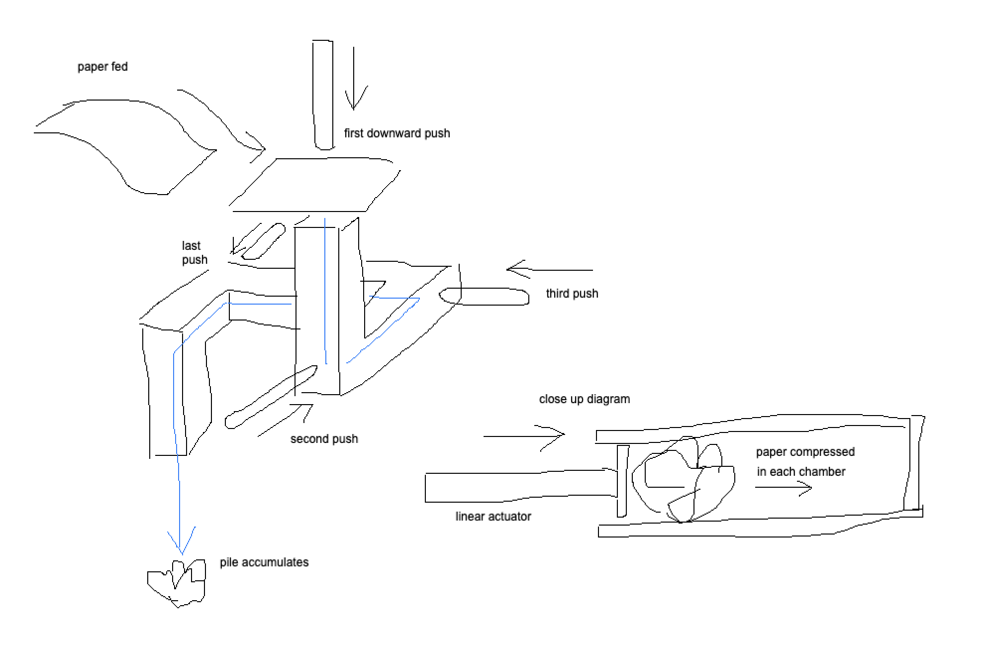
Paper is pushed and compressed into a series of chambers using linear actuators. I am yet to actually test if this works, but it is currently the easiest (or most simple) process I have come up with that I believe will achieve a consistent scrunch.
I am thinking of using the goBilda linear actuator found here. However, I can only afford at most three of these. The alternative is to 3D print linear actuators, but given time constraints I want to avoid this.
The way I see it, this project has two main problems:
Feeding a single sheet of paper into the initial position, and
Scrunching the paper
Problem 1 may be solved by making a feeder similar to this. However, this also seems incredibly time consuming and fiddly to build. I am searching for something a little less complicated.
Problem 2 may be solved by what I have posited in the diagram above.
Before I make any purchases and start piecing together my project, I wanted your feedback. Does this seem possible? How else could I approach this?
Heaps of variations if you search "servo linear actuator.
Here is a short one I printed to push a piano key but you can scale up easy.
Super cheap and its been desinged for you so it doesnt impact your time constraints.
The go builda stuff will work too im sure.
To solve feeding the paper into the right spot what about a printer and a paper tray. It would sell the themes your exploring and printers are cheap if you dont need ink.
I agree with @Pixmusix on this one, if you’re wanting to save some money and have access to a printer making your own servo based actuators would be a cost effective way to get what you’re looking to do done.
The 3D printed linear actuator with a servo is a great call. It looks like a relatively simple device too.
Do you have recommendations for the types of servos? Would this guy be overkill? 10kg of force per cm. I want to make sure the paper is scrunched.
I haven’t worked with gears before, but I assume if I start with a large gear on the servo (increasing movement at the gear’s circumference) I can push the “linear actuator” faster and a further distance. Looks like fun.
I know a printer and paper tray may solve the feeding part of the project, but I want to keep the same “ecosystem” throughout, i.e., all 3D printed parts and electronic components, no existing objects. I may circle back to the printer if my experiments fail.
Sounds like you’re on the right track with your understanding of gears; the larger the gear the faster the actuator will move. One thing to note is that with the designs shown above the gears are only there to translate the rotational force of the motor into the linear force of the actuator. The amount of teeth used would have no impact on the forces or velocities. Basically instead of gears you could use a rubber tire on a flat surface and achieve the same result.
In selecting your servo the 10kg of force is per centimeter of distance from rotation, as discussed above this is exactly the size of your gear. For example if your gear has a radius of 2 cm the actuator would be able to push with 5kg of force. (This is ignoring the effects of friction, deformation, etc etc). In order to narrow down your search I’d suggest doing a simple experiment as follows:
Get a tube that would be roughly the size of the tubes on your machine and place on a set of scales.
Zero out the scales so that you’re not measuring the weight of the tube.
Push the paper through the tube as the mechanism would and observe the highest value outputted by the scale.
This should give you a reasonable estimate of how much force your mechanism needs to produce.
Give yourself a margin of error, for example if you need 7kg of force, ensure your mechanism can provide 10kg. Alternatively just get the most powerful servos you can afford as more destructive power can’t be a bad thing…
Another thing to note is the servo linked can only rotate it’s shaft 180°. A continuous servo can rotate without limits and is probably a better fit for this project as it means the distance traveled is not limited by the size of the gear you use.
A continuous servo understands what zero is, a stepper needs some form of limit switch in order to detect its zero position. With a continuous servo you need to keep track of the number of revolutions (if it’s more than one). With a stepper it is simply a count from the zero position. If I was doing this I would use a stepper and limit switch because of the more flexible control system and the greater number of options available.
Hello all, I will add a silly to the Scrunching Machine and suggest a Flushing Scruncher. Liquify the process, under a controlled process of course.
Bryan
Some great suggestions from everyone here! Just jumping in to make a suggestion for the contact point at the end of the actuator.
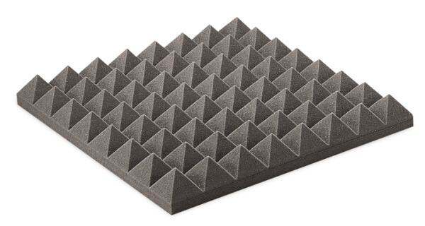
I think that you may have a more impressive ‘scrunch’ if you introduce as many creases in the paper as possible with each compression. It sounds like you may have access to a 3D printer, so this should be something you can experiment with. The first thing that comes to mind is making two pyramid grids that fit into each other so that when you squash the paper in between them, they create lots of smaller creases instead of a few big ones, as would happen with your rod and tube sketch.
The closest image I could find of this shape is sound-deadening foam, which would be too soft to use for this, but should give you an idea of the squashing plate I am thinking of.
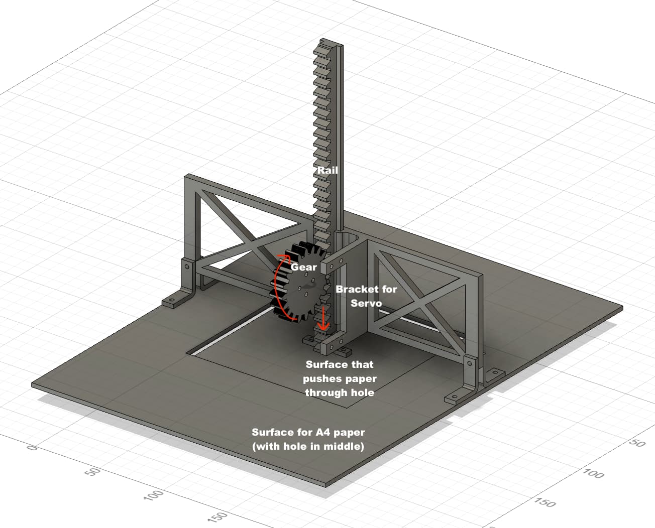
Thank you @Pixmusix for the servo linear actuator design. And thank you @Samuel for the contact surface ideas. Both of these features I have incorporated.
I am currently 3D printing the pieces and will laser cut flat sections by the end of the week. Once it is assembled, I will know if it works or not (or is a feasible idea to pursue).
Thanks for the help so far. If you have any other suggestions, it’d be much appreciated.
Thanks for sharing your prototype and the Fusion 360 screenshot, it’s great to see the design coming together! Awesome to hear you were able to incorporate the servo linear actuator and contact surface ideas from @Pixmusix and @Samuel. Keen to see how this one progresses!
I seem to recall one of those production house logos in the 80s at the end of the credits being a little fancier than usual; a stylised animation of a writer pulling a sheet of paper from a typewriter and ditching it somehow… Might have been at the end of Family Ties or something around then