As far as I know PD stands for power delivery
EG Volts and Amps if I’m wrong I’m wrong.
And the Pi5 requires a PD power source too get full potential, the Pi ask the power supply can you supply this and the power supply shows at this voltage I can give you this (in a roundabout fashion)
So I just want that, nothing more just a PD interface that will tell the Pi that the 5V power supply can give it the 5A out of 6.5 available.
Or if I really wanted to break out a 5V 60A filtered regulated power supply (PSU)
And if I really what too break out the Oscilloscope and check the rectified output.
Thank you to all for your help but I think this one is done.
Hi Bob,
This post has been an excellent learning experience for me. Initially I didn’t know what PD stood for, but when I searched for USB-C PD it became clear. I can think of many other things PD would stand for too, ‘Personal Development’ for one. I have found similar problems with other posts when the abbreviation used is not in the forefront of my thinking. Have to mentally shift gears.
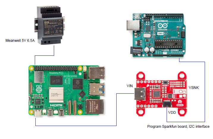
After I understood what Aaron was trying to do, I didn’t see how it would be possible using the Sparkfun board I linked. The board will be used opposite to what it is intended, I think. The Meanwell supply will be connected to the Sparkfun board and the USB-C to the Pi5. Another micro will be used to program the Sparkfun board to tell the Pi the supply can deliver 5V 5A. Possibly this will work.
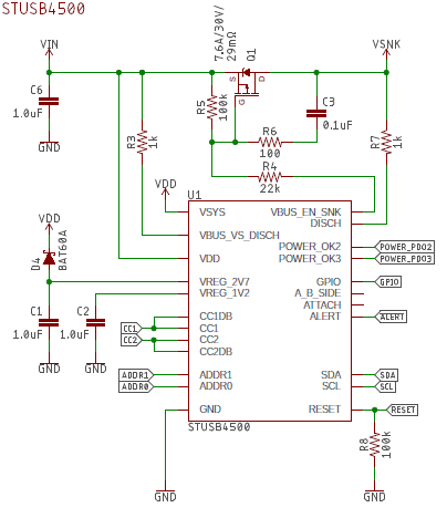
The schematic shows a mosfet between Vin from the USB-C connector and VSnk connector. this would have to work backwards and don’t think it would do that nicely. The mosfet is controlled by the on board chip. The drain source diode would be forward biased and high current would kill the mosfet.
An alternative would be to just use the messaging of the Sparkfun board only and the Meanwell connected to the GPIO 5V pin. Again I don’t know if the PMIC chip on the Pi 5 would like this.
I wish Aaron all the best and hope he lets us know how it goes; as it might be something I would want to do when I finally get a Pi 5.
Cheers
Jim
PS The official Pi 5 documentation is well worth a read with respect to Powering the Pi. Especially where it says :
While USB-PD capable phone chargers advertise greater than 15W of power, virtually all of them achieve this by increasing the voltage instead of providing more current at +5V. If you are using a power supply that cannot provide 5A at +5V on first boot you will be warned by the operating system that the current draw to peripherals will be restricted to 600mA.
Probably that is the way the Powertech device I linked does it. Which means it would not work with the Pi 5.
Hi Aaron
Yes, these days apparently it does. I did not know this until quite recently. Ever since I started in this electronics business (1964) it has been an abbreviation of Potential Difference. Obviously I have not kept up with the times.
I have not looked at this in any great detail (and am probably not going to) but as I understand it this system communicates with the SOURCE SUPPLY to say it needs or can use X volts at Y current limit which your Meanwell cannot do (communicate) primarily for battery charging.
Looks like you want to go the other way, that is tell the Pi that you have 5V @ 6.5A available. I am not sure how this is done or if you can actually do that. I would think that connecting the 5V to the Pi and let it take what it needs would suffice. Is it possible that the 5.5V is considered too high and you need to turn the Meanwell down a bit but you say you got the same result with a 5V bench supply so maybe that is not a factor. I would check your insertion point. Also sometimes you can’t use an external supply and USB supply at the same time which means for most situations you can’t have the USB cable connected.
All a bit flakey still.
Cheers Bob
1 Like
Hi James
I have been confused by overuse of unrecognised abbreviations for a long time now. OK for the author but if they make them up as they go along (which often seems to be the case) it is almost impossible to decipher. For instance using “USB-C PD” would cause me to investigate what this version of “PD” was instead of blindly translating to “Potential Difference” which is what I have known it to be since 1964 or before
You could read “most” instead of “other”. could not agree more.
Cheers Bob
Hi Bob,
Basics of Power Delivery (PD).
- When the USB-C ports are connected.
- The source (Pi 5 plug pack) sends a digital message to device (Pi 5) saying what power it has available.
- 5.1V/5A, 9V/3A, 12V/2.25A, 15V/1.8A
- The Pi 5 then sends a digital message asking for 5.1V/5A.
- The plug pack then sets that as its output.
This happens between the PMIC chip on the Pi near the USB-C connector and whatever chip is in the plug pack. (STUSB4500 chip on the Sparkfun Board)

The Pi OS can then read the setting from the power management chip.
If it doesn’t say 5.1V/5A the software limits the current to 600mA on the standard USB-A ports and reports it in the GUI. The PMIC chip may check the actual voltage, unsure about that, have not looked into it in that much depth.
Suffice to say if Aaron wants to use the Meanwell supply he has to trick the PMIC chip into thinking all is good. The Raspberry Pi Corporation will probably take a dim view on this and consider any warranty void. It is not being used as they designed it or intended it to work.
Considering this type of thing may become more popular as time goes on, there will eventually be a software work around. The real problem is the Pi 5 will limit the current to the USB-A ports, if it thinks the supply is inadequate. It will probably limit the current to the Ethernet connector, making some power over ethernet applications not work either.
Regards
Jim
PS This has been one of the best learning experiences I have had on this forum. I now feel I understand USB-C power delivery much better than I did before. It also explains some experiences I have had with USB-C and why it did what it did.
1 Like
Hi James
I think I am getting to know this a bit better now too.
Please correct me here if my thinking is wrong. In a nutshell this Sparkfun device sits between the Pi5 and power supply and emulates a “PD” capable supply. So if Aaron connects this Meanwell supply to the spark fun bit (as VDD??) the maximum voltage that will get to the Pi5 will be 5V. To get the full capability you need to have a supply of 20V+. Maybe because this extra voltage is not available is the reason the Pi5 returned an error saying not enough power. Interesting.
I knew there was a reason I try to stay clear of RPi.
Cheers Bob
I could be wrong too, but this is my understanding.
-
The way Sparkfun intend the USB-C PD to be used.
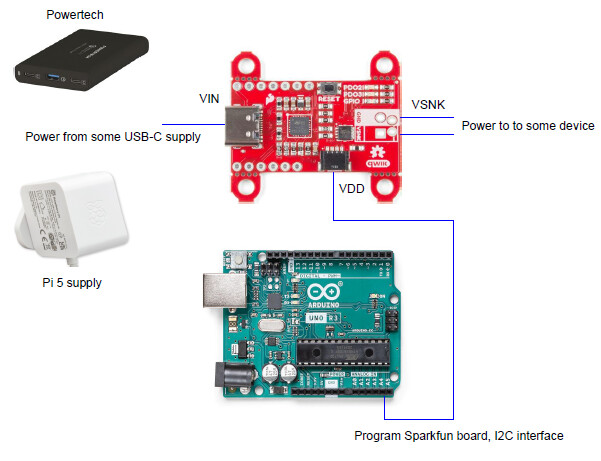
-
The way I think Aaron wants it to work.
The Sparkfun board is programmed to say it has 5V/5A to the Pi 5. I think there are smarts in the PMIC chip that wont allow this to happen.
VDD is the power for the I2C interface to the Arduino board.
The following is from the Sparkfun schematic. Proper current flow is from VIN to VSNK, you cannot connect the Meanwell to VSNK and expect it to work in reverse. The mosfet diode would be forward biased.
Anyway hope all this makes sense.
Most of this is just me reading the how to, analysing the schematic and the USB-C standard.
Regards
Jim
2 Likes
Hi James
Don’t know what example 2 would achieve.
I think the logical connection would be Meanwell (5V) to VIN, VSNK to Pi and Arduino to I2C as you have shown.
Now the point I have been trying to make is that you have only a 5V input (Meanwell) so you can only possibly have VSNK 5V. So what is the Sparkfun for. Why not just connect the Meanwell supply to the Pi. All the Sparkfun device could do is be a pretty expensive current limiter. Might pay to turn the Meanwell supply down to 5V. Aaron has not said what model Meanwell he has but if it is like mine there is a small range of voltage adjustment available.
Aaron has presumably sorted this or pt it to bed anyway so I am not losing any sleep over it either.
Cheers Bob
2 Likes
Hi @Aaron53495,
How are you connecting the power-supply to to the PI? Are you connecting to the 40 pin header? Or do you have a USB-C plug that you have connected to the MeanWell supply?
The reason I ask, is that in my early days of Raspberry PI I had a very hard time finding a plug without a lot of internal resistance. Have you used a multi-meter to check the voltage as received by the RPI on the 40 pin header?
Kind regards,
Gary
1 Like
Garry
USB-C, minimum of 0.5mm2 to get the cable current carrying capacity.
I measure at the supply, GPIO and the USB port. and I am using the Pi is to get voltage and other info.
PSU 5.19V
GPIO 5.15
USB-A 5.15
0.04V drop on no load, should be less.
PS all my equipment is also calibrated every year. by Regulations.
Check out the Pi 5 Documentation, it is verry helpful.
I should have gone there first, then I would not have posted here.
That will teach me to be Lasy.
Regards
2 Likes