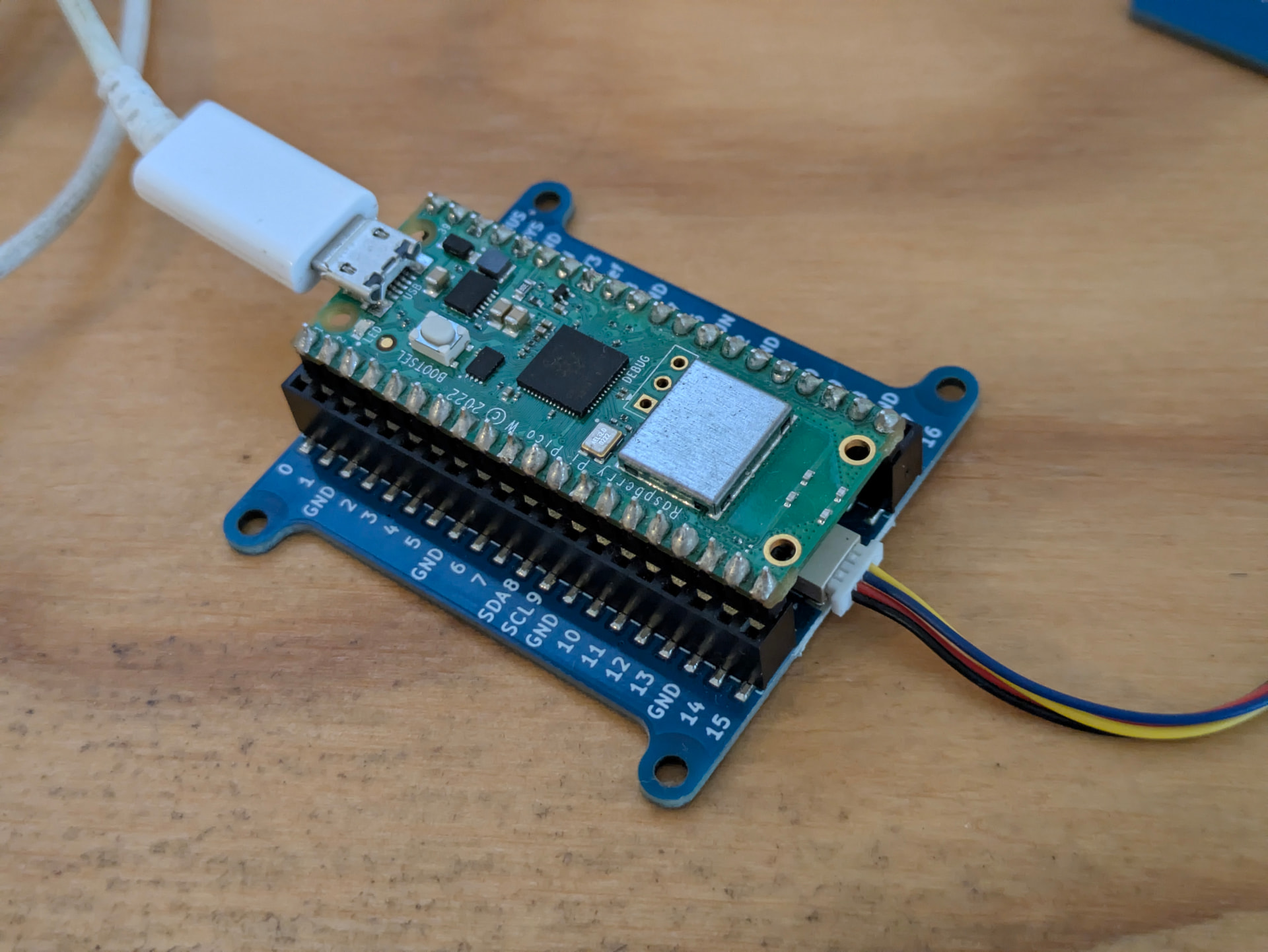
I’m having continuous issues with the little piicodev connections dropping out and breaking my project. I’m hoping someone can offer a solution.
I have 12 Picos 2 W each with 3xRFID scanners and 3x buzzers daisy chained.
I frquently get the EIO error, and have been assuming it’s the physical socket connections. Each time I’ve messed around with disconnecting/reconecting/rebooting etc. Sometimes works, sometimes doesn’t, but it doesn’t seem to be obvious where the issue is.
Before using Pico 2 W, I was having the same issue the RPi Nanos.
As I say I’ve been assuming this is a physical connectoin issue. If anyone has a solution to improve the connections continuity aside from soldering, I’d really appreciate it.
Has anyone had any luck with hot glue, as I’ve seen people succesfully do with Arduino pin connections?
I found some 2022 posts the other day regarding a MicroPython bug causing I2C connection issues. This sounds very similar to the issues I’m having. Does anyone know if this bug has actually been fixed?
Would be great to get to the bottom of this as it’s really causing big issues with my project, and I’m not sure if it’s the software or hardware.
Although I’m using Picos 2W (pictured) instead of RPi Zero and the longer version cables.
Now that I’ve switched to Pico, if the scanners/connections drop out apparently more often than not powering of and on gets the scanners working again, but this is not a workable solution. And still sometimes disconnecting the connections and reconnecting them and power cycling is still required.
I took this to mean the connectors were physically falling out of the mating connector. Now I think you mean the connection is “dropping out” as in losing communication. Can you clarify.
When you say “X 12” do you mean you have 12 of this set up including 12 Pis or are you arranging 12 strings as shown on the one Pi and using 3 of those expansion devices.
Looking at that one string of PicoDev things first. What have you done with the I2C pull ups. There is a strong chance that each PicoDev thing has its own pull ups. This would make 6 sets of resistors in parallel. This could be straining things a bit as if the on board pull ups are 10kΩ then 6 in parallel would be effectively 1.66kΩ. A bit low methinks when you consider I2C would be designed for 1 pull up. It can stand more but 6 ???.
Things could get far worse if you have 12 of these strings connected via that expansion thing. The I2C lines would have to be isolated you would have an effective pull ups of about 0.14k (140Ω) pull up on each line. As the data line is bi-directional I don’t see how the expansion ports could be isolated.
I think we need a complete diagram of your set up to comment much further. Maybe your “drop out” problems low value pull up causing a power supply struggle or good old fashioned data overload on the poor old Pi. By my reckoning you have 6 devices on that string and 12 strings. A total of 72 devices.
Cheers Bob
Yes, I have 12 of this set up including 12 Pis. So 6 devices daisy chained to each Pico.
Yep, each PiicoDev device has its own pull ups. I haven’t touched the I2C pull ups.
Reading the connections guide I thought I might get away with 6 devices: PiicoDev Connection Guide - Tutorial Australia
Do you think I should cut some of the pullups, what would you recommend?
I have not looked at these 2 links ut I did look at the PicDev Lipo expansion board schematic generously linked on the topic below. Not often you can get a schematic. But having said that it does not show the USB input connector, Just the I2C connection (with 3V3 power output) and battery connector.
This says there are pull ups of 4k7 on the I2C lines on that board. Now if there are pull ups of 4k7 on the other 6 boards that makes a total of 7 sets of pull ups and if they are all 4k7 the result would be 670Ω. I think way too low.
I would try to remove the pull ups on the first 5 devices and just leave them on the expansion board and the last device on the string and see what that does. The only damage you would do will be physical depending on how gently you carry out the removal task.
Cheers Bob
Sorry for the delay in getting back to this discussion.
At a glance all of the connections look sound (I’d move the buzzer away from the RFID antenna on the end though).
Have you performed any testing? For example, testing the stability of 3 units, seeing how they behave, then adding more?
Bob’s suggestion of removing the pull-ups is sound and hopefully fix the issue.
That makes sense now it has been pointed out. As the schematic is only that of the expansion board you only show connections to that board. I should have realised this.
Cheers Bob
EIO on I2C is usually hardware related. Not software in most real systems. Your setup is very large and complex. Twelve Pico nodes push I2C limits hard. I2C is not designed for daisy chains.
Long wires increase capacitance and noise. This causes signal loss and random errors. RFID and buzzers add electrical noise spikes. Improve power filtering near RFID modules. Test with lowering the I2C speed. Mechanical fixes like hot glue do nothing electrically. Only physical stability improves slightly. Connector quality also matters in these systems. Poor pin connections increase resistance and instability.
Hi Love
If you care to return to posts 3 and 5 you will find on post 3 a RPi with a string of 6 I2C devices.
On post 5 Anthony says
which indicates to me that he has a RPi device with a string of 6 I2C modules and this is repeated 12 times. He does NOT have 12 nodes on 1 RPi.
I believe that is just what I2C IS designed for. Admittedly it is meant for short distances like the original use was between IC groups or between boards in the one equipment. NOT over any appreciable lengths of cable.
Capacitance between wires can be minimised by using low capacitance cable and noise and common mode interference can be just about eliminated over quite long lengths by using balanced and properly terminated lines techniques. Think telephone wires, can be several km.
Be very careful here. Try to NEVER have a filter or capacitor to ground on BOTH ends of a wire. One end only. Indiscriminate addition of capacitors throughout a circuit to supposedly eliminate “Noise”, whatever that is, can and often does result in lots of tuned circuits which can actually enhance induced interference greatly at these frequencies.
Cheers Bob
Just adding some thoughts here, which may or may not have been checked.
The following is based on a google search so may not be 100% correct with the values.
From a google search the Pico 2 W and RPi Nano seem to have the same power limits on its 3.3V rail; 300 mA. That would need to cover the Pico/Nano itself as well as anything else connected to that 3.3V rail.
The Buzzers seem to be 15mA to 25mA, which I assume is when buzzing.
The RFID seems to be about 10mA
So if we have 3 Buzzers @20mA and 3 RFID at 10mA we have 60+30 = 90mA
That leaves about 210mA for the Pico/Nano itself.
I do find it interesting that you comment that you have the same issue with both, so this could be something in common.
So now, how much power dies the Pico 2 W use ,
Google AI response The Raspberry Pi Pico 2 W uses roughly 15 to 25 mA** when idle and can peak up to **300+ mA** during Wi-Fi/Bluetooth radio activity....
So we have 2 devices where the 3.3v regulators seem to just cover what the pico may need under its peek load before we add the rfid and buzzer nodes.
Based on that, is it possible that your just running out of power ?
If you have a USB power monitor you could see if it gives an indication.
3.3V * 300mA = 0.99 Watts / 5V = 198mA (not including any lost power in the conversions) ; Also keep an eye on the 5V level. If that’s dropping too much it means the 5V supply (usb) is not keeping up.
Hi Michael
Good thoughts.
Does all these estimates include the loading due to all those pull ups.
Anthony has not responded to my suggestion re removing all but 2 sets of pull ups yet (18 days ago).
A good trouble shooting move would be to eliminate each suspected cause in turn to try and isolate the problem.
The board pull ups are a low 4k7 and if each of the PicoDev modules are anywhere near that (I don’t know exactly what they are) the resultant resistance would be very low.
This suggestion was made 18 days ago now so if Anthony does not see fit to try this fix and report back I am afraid I don’t see fit to worry too much about his problem.
On the same subject surely the designers of these modules could provide a couple of link pads to give the end user the option to include pull up resistors or not.
Getting back to your post. I think your “just a thought” is very valid.
Over many years I have found that a significant percentage of fault in pre designed commercial devices can be tracked to power supply problems of some description. The instance of problems of this nature with experimental situations on a hobbyists work bench is probably somewhat higher.
Anyway personally this is my first go to area when a problem seems to come out of nowhere.
Cheers Bob
PS" Remember that if a power source is falling down for ANY reason the whole thing is usually falling down with it. Thus I believe the power source is the most important area. Without it you have NOTHING.
I did not to the lower level math, just the high level what it “can” provide and what the units “can” draw… It was enough for me to say "… depending on what is running, e.g. wifi radios; or what its driving; their may not be enough power… "
If Im looking at the same module… the schematic shows you can disable the pull ups by clearing the pads
The i2c pull resistors on that board I have are 10K and the schematic for the buzzer shows the same cut pads and 10K
So 7 (6 modules + controller) * 10K pullups = 1428.57 ohms (ie 10K in parallel)
So the I2C driver would need to sink V/R = I .. 3.3/1428.57 = 0.00231A => 2.31mA, which is still below the 12 mA max sink of the pico 2w GPIO pins; not sure what the module chips can happily sink to ensure a full pull down.
If Im looking at the wrong board and the pull ups are 4k7
7 of 4.7K = 671.43 ohms. 3.3V / 671.43 ohms = 4.92mA .
It is the expansion board that has 4k7 pull ups. The 10k on the other boards are a bit more realistic.
I have some humble apologies to make to Core re schematic availability. It seems I am making these apologies more frequently these days. Must be related to age. I am sure that last time I looked, which was some time ago, there were no schematics for the PicoDev range readily available and I had my usual rant about this. It seems that has been rectified as the schematics are there for the 2 modules concerned in this thread anyway. The pull ups are easily removed and replaced also so all good.
I am afraid I need to do more research before I open my big mouth in future. I promise I will try.
This makes the job of pull up removal and replacement a much easier task. So Anthony have you tried my suggestion about removing the pull ups on all but the ends of the string or haven’t you. Would be nice to know.
Cheers Bob
Hey guys, thanks for your input on this thread. I did pass on recommendations for removing most of the pullups but I’m yet to hear back of the results.
I haven’t been able to replicate the issue at home, and the project is interstate so it not that simple to spend days testing and debugging on site.
To quickly answer a couple of points, the picos are not using wifi, that was for a backup option, and a specific buzzer paired to an RFID scanner only buzzes after an RFID card is detected, read, and written to successfully. So I guess idle power use would be the pico and the 3 RFID scanners.
Using the RPi AC adapters output 5.1v 2.5A
I should hopefully have some feedback later this week
Oh Great. After 15 posts we now find that it is not you having the problem. You are the go between for someone else who is not even in the same state. You might be the one designing the system but that is as far as it gets.
The worrying bit is that those pics are probably not the system under scrutiny. It apparently works with this set up
but what guarantee is there that the remote installation is the same. The cable lengths could be much longer in practice and if too long could be the problem. The recommended cable length for reliable I2C operation is apparently measured in mm. Some have claimed use at over 1m but I did mention “reliable”. I think this has been done by throttling the data speed back to some sort of minimum rate.
It is my personal opinion that trying to remotely trouble shoot your problem under these conditions has made its way into the “almost impossible” basket. Trying to do this 2nd or 3rd hand to me is not an option. It is my experience over the years that every time some information is transferred via a third party some distortion occurs, sometimes (read mostly) serious. So we have info coming from site via you and suggestions going back to site once again via you with now no real confidence of the absolute accuracy. Not a good scenario.
What about the hours and days on research and head scratching on this side of things. Not to mention the days waiting for feedback that often never comes. That does not count I suppose.
This has suddenly started to smell like a commercial operation now anyway.
Cheers Bob
Hi Anthony
All OK now we know exactly what is going on.
BUT. What is going on EXACTLY at site is all important.
You say the set up at your home works OK. So there is a difference. Showing pics of your home set up is pretty meaningless. There is obviously a difference. We need to ascertain what that difference is and you are probably the only one who can do that.
One obvious difference could be cable lengths.
I have not looked closely but I believe the I2C system was designed to provide full duplex communications between sections of a system on the same board or at worst boards in the same box. Or in other words just a few centimetres. It has been stretched to include comms between modules which could be some distance apart due to project requirements. Your project could be one of these I suspect as I cannot see much use for 36 RFID/Buzzer pairs just a few cm apart. Even groups of 3 (12 groups) at just a few cm apart would be hard to imagine.
So, just exactly what are your cable lengths. Mechanical installation sketch reflecting this please.
Pull up resistors. I stand by my earlier comments and I believe pull ups on ALL of the modules is too many..
Although I have no experience with I2C over more than about 10cm I do have experience with data comms over longer distances. Like RS232 over more than a couple of metres. Using low capacitance cable and different wiring techniques you can get 75m or more with this system. Over longer runs still a balanced line system like RS422 (one way) or RS485 (half or full duplex) are the go to systems to use.
I have had an idea for a while that it may be possible to extend I2C usage over longer distances by utilising the same wiring techniques as used to extend RS232.
Unfortunately I don’t have the space or facilities to conduct any testing that would be involved.
If any one does have the necessary and is interested I would be happy to provide details. My idea would require a cable of 3 twisted pairs and if using those little connectors some sort of breakout as I think terminating 6 wires in the connectors would be very difficult. The limit here would be how far you can go without terminating the cable as I don’t see a way around using terminations AND pull ups at the same time.
Cheers Bob