PiicoDev RFID Module (NFC 13.56MHz) Max Cards

I have been playing with the PiicoDev RFID module which is based on the MFRC522 chip.
ie: PiicoDev RFID Module (NFC 13.56MHz) | Buy in Australia | CE08086 | Core Electronics

Im just looking for some feedback from experience and/or some ideas.

I have the device up and working and can use more then one… and I understand RFID fairly well.
With the 14a RFID ideally we only want one card in range of the reader at the same time, this allows the identification and card selection based on the tags UID to be simple and works. But the 14a standards do allow more then one card to be on the reader at the same time and with the use of the anti-collision and tag select commands we can isolate and tags UID then select it, while all other cards stay quite.

My anti-collision code seems to be working with 2 cards.
i.e. We send the REQA/WUPA then anti-collision/select level 1 (0x93 0x20) and we get the detected location of the first bit collision. I can then use that to select a part UID and get the remainder of the UID for 1 of the two cards.
i.e. the reader does detect the correct collision bit location and I can select one tag, then the other as needed.

But when I put 3 or more tags on the reader, i get nothing, just a time out. i.e. no data, no bit collision location, nothing.

Do we know if there is a limit on this chip to only work with 2 tags.
I have played with the field power levels and data bit and collision bit thresholds via the registers but still nothing.

So to be clear.

  1. Selecting reading/writing to a single tag - no problem
  2. Selecting one card from 2 cards on the reader (either one) - no problem.
  3. When 3 or more tags are on the reader, I get nothing.
1 Like

The MFRC522 IC used on that device has no exact reference circuit; it’s an iterative design process that has calculated adjustments based on real-world performance.

The functional envelope you see today on that hardware may work up to a point, which enables enough RF bandwidth to handle what you’ve just experienced. Pressing further may involve more experimentation to get more functionality from it.

Eg, likely not a software issue. This is more likely deep in the RF-magic zone of hardware design.

1 Like

Thanks for the feedback Gramo.

I suspected the rf energy may be getting a little low with the extra tags; and the collision reference could vary up/down depending on how many tags had a 0/1 in that position.

I have some PN532 and PN5180 dev boards coming to see if they have some more grunt as they are newer chips with new features.

Ideally I would like to select 1 from 5/6 tags, but might need to move to Iso15693 for this project (hence the PN5180)

1 Like

If any of your cards have a 7-byte UID, they require Cascade Level 2 handling (0x95 0x20 instead of 0x93 0x20). Be sure your anti-collision logic supports:

  • Full UID tree traversal
  • Checking CT (Cascade Tag) bytes

If you’re stopping after only Level 1, 3+ cards (especially with mixed UID lengths) may break detection.

1 Like

Yep, all valid, and no issue with cascade.
The issue is that with 3 cards on this reader, i get no data back at all from the level 1, so no cascade byte to check are select to move on to level 2,

I will see how I go over the weekend, and I might put a scope on the antennal coil so see what it looks like.

Hi Michael

That would be interesting. Might not be much in the way of voltage and might not mean a great deal if your scope probe disturbs the antenna system too much. You could find that it does not work too well at all with the probe on there.

But you never know with the black art of antennas (it might even work better) so will be interesting to find out.
Cheers Bob

Yeah, but I can normally get enough. I am normally looking for the difference as apposed to exact values; as you say, you are adding to the antenna.
Its an inductive loop of AC based around the carrier freq., in this case 13.56 Mhz

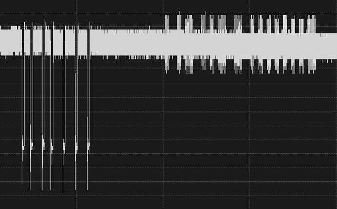
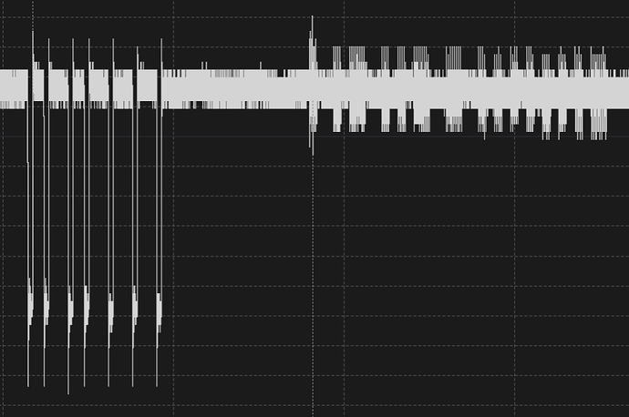
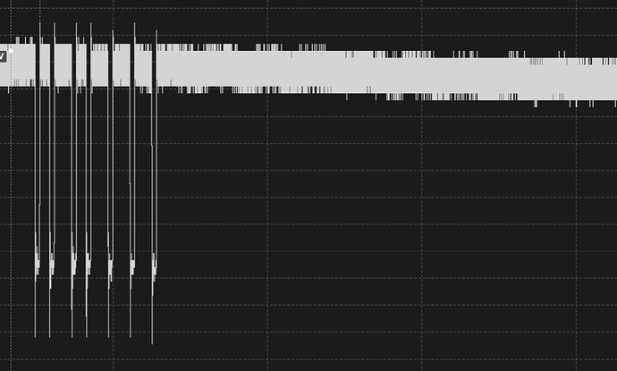
OK some quick scope probing…

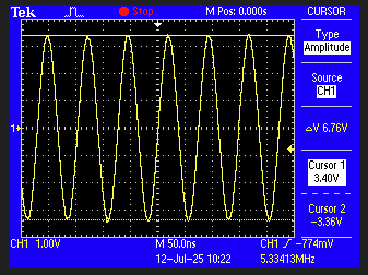
  1. No cards, just field on

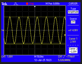
  2. With 1 card

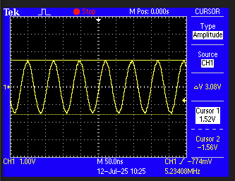
  3. With 2 cards

After 2 cards, it could not really detect any more drop in power.
This could indicate the 3rd card was having trouble getting/pulling power (as it will need to draw some power)

So if 2 cards and 3 cards don’t cause a power drop, then why no data? … my theory is while the carrier did not drop, the actual bit collision and data bits will need to be captured to see what they look like.
i.e. the tag will put a load on the carrier to modulate a signal.
So I will see if a cant collect some high speed samples.

Hi Michael

If this is your pick up loop for your scope probe then it would be nearly non invasive and cause minimal disturbance. 13.56MHz seems pretty low but I have zero experience in this application. A resonant antenna at this frequency would be pretty large.

The tag has to be powered. This power has to come from somewhere. Obviously from the received carrier.

I note that 1 card causes about 3db drop, 2 cards about another 3db (approx) while additional cards appear to cause no change.

Maybe about 6db ( down to about 1/4 power or donating 3/4 power whichever way you look at it) is all the host transmitter is prepared to surrender or donate to cards. Could it be that this host is designed to operate with cards that have a more modest power requirement. Could be something to ponder. Leave that in your capable hands.
Cheers Bob

Yeah, with all of these modules (as pointed out from @gramo above, can/will have limits based on their design and needs.

The antenna is an inductive coil so kinda different then a normal radio antenna so small PCB antennas can work well at 13.56 Mhz, just need to be tuned.

With 13.56Mhz RFID, its not really for multi tag and the anti-collision is a best effort. A collision, in theory will cause a relative different load on the transmitter/reader field. So will come down to
a) Enough power getting to the tag to power it.
b) The reader being sensitive enough to tack loads and their level.
Antenna coil voltage can vary a lot. and 3.3v is fairly low. My RFID hacking tool will work at about 45V at the coil and that has been shown to work with 10 cards at the same time (under their test setup). But if you idea is to keep power needs down (e.g. quiic bus power) then their is nothing wrong with lower power levels at the expense of only dealing with 1 or 2 tags. i.e. a design decision.

The PN5180 which can do 14a and Iso15693 as a logic supply of 3.3V and chip supply of 5v. The Iso15693 had more effort put into multi tag reading support, so could be a better choice anyway.

Note: I don’t really have an issue if this unit cat do it, as it is what it is, so at this point its more academic and interesting.

Hi Michael

Pretty right here I think.
As I see it the idea here is to get a concentrated magnetic field in a small space so a card in close proximity can gather enough energy to power itself. It won’t radiate much as most of the energy is used to provide this field.

All coils are inductive (except maybe bifilar wound ones), it is the nature of the beast. Even a straight piece of wire of a few cm has a measurable inductance.

Don’t know what would be considered a “normal” antenna. The ones of resonant length I would think. These could range from “broadcast band” to parabolic microwave dishes with waveguide. Any one would be “normal” if used in the situation they were designed for.
These would include Ferrite rod broadcast receiving types (the TX side is usually quite high vertical radiating structures), Long wire, resonant half wave dipole, Vertical quarter wave whip, Yagi, Log periodic, Rhombic, Helical.

There are many VHF designs usually complete with their own ground plane in the form of horizontal rods. Also many variants like Co-linear array or stacked array combinations.
The one which really stretches the “black art” imagination is the “Slot” antenna, used mainly at VHF frequencies. It is basically a rectangular hole cut in a sheet of metal and yes, it works.

As I said all of this would be “normal” when used as designed.
Cheers Bob

Yeah, normal…
I was thinking more an induction v radiating. i.e. radiating (as we all know) would be tuned to the frequency e.g. 1/4 wave, 1/2 wave etc. In rfid, its more a coil whos physical parameters can best transfer the energy over a short distance at the carrier frequency. (some readers will claim 100-150mm, but it would be more like 50-100mm (or worse on some readers).

the key idea of the very short distance is to not have more then one card in the field. Think eftos, it would not be ideal to read from 2 different tags then randomly select one to charge. Even worse if the one it chose was the person behind you.

One rfid challenge has always been “antenna” alignment. the PCB “coil” is often a different size and and/or shape to that in the tag (e.g. Full size card or a fob or an implant).

the energy from the readers coil can also be seen as RF, but the load on that coil from the tag is very hard to see (via and SDR or simular). As we know, what the theory says the wave “should” look like is not always what we see when we measure.

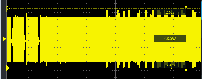
but for an example.

The short “deep” gaps on the left are part of the reader sending data to the tag.
i.e. it cuts power for a set amount of time, then allows full modulation. Its a form of Manchester encoding, where if the “drop” is in the middle of the bit period, then its a “1” bit, if the drop is at the start or missing, its a “0” bit.

If we compare that to the wave on the right hand side, we cans see the “high” part peek out, i.e. no load from the tag, so the carrier is “stronger”
This is also Manchester encoded, but this time the High/Low are of equal size/duration. so a HL = “0” bit and a LH = “1” bit (where H is high and L is low)
(but can be inverted.

What you kinda notice is when the tag is talking, it can stop collecting power, thus the amplitude gets higher, then back to taking the power, which will pull it down.
So if we had two cards taking power, while they are sending the some bit, the pattern should be similar, just and overall smaller amplitude. The moment we have a collision (different bits getting sent) then one will not be loading and one will, so, this in theory should be a different amplitude reflected. If we had 3 tags, two would have the same bit, 1 would be different, so now we have a bias thing happening.
i.e. the actual voltage read at the reader needs to consider all of that to work our if the different levels is cased by a card moving in the field (getting closer etc) or if its the effect of 2 or more chads in the field.

1 Like

And just for reference.
Note: This was captured on a logic analyzer and the sample rate is not ideal for 13.56 mhz signal… but it seems good enough to get an idea of the signal with 1 2 and 3 cards.
All 3 show the same start of comms. i.e. REQA and the tag response.

1 Card

2 Cards (while not an ideal capture, it looks like the card/rag modulation is lower then with just 1 tag.

And 3 Cards… cat see any card/tag response

1 Like

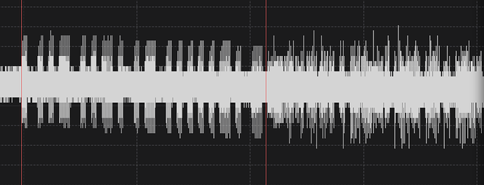
And a capture of when the collision happens
the bit between the 2 red lines is the bits in sync (some on both tags)
After that there will be a mix of different bits and same bits. Some quick math and knowing the UID the first collision seems to be in the correct spot

2 Likes

Hey @Michael99645 ,

Thank you for sharing your thorough observations, and it’s excellent to see the helpful input from the community. Your practical insights into the MFRC522’s multi-tag limitations are very valuable.

1 Like

I do want to stress that I think these little readers are a great little reader. We just need to keep in mind the intended purpose v what I am working on.
i.e. they are designed to be small, affordable and cascade on the Qwiic bus.
So that makes a great little rfid reader for a quick project.
On top of that, if you have the time you can send raw APDUs to the reader to read/write to other 14a cards as well, just you need to do the the authentication and encryption in your code.

2 Likes

Hi Michael.
We digress a bit here. BUT

From a professional viewpoint the “should” and “actual” had better be the same. And usually is providing the instruments used and the techniques are compatible with the measurements taken. You need to be able to say with some certainty that when measuring say the performance and characteristics of a transmitted RF signal that what you are seeing is actually what is transmitted. Otherwise you are really wasting your time.

But, having got that off my chest as the saying goes I know that the equipment required to make such measurements cost sometimes hundreds of thousands of $$ so is way way out of reach of the average hobbyist and some of this is something most would really only dream about. Of course you then have to know how to use this nice gear.

I guess what I am trying to say is most of the discrepancies between “should” and “measured” could be attributed to instrument type and technique. But as I have stressed on many occasions if you are aware of any shortcomings with what you have available this need not be a disaster. If you know what the limitations are with instrument and technique some sense can usually be made of your result.
Cheers Bob

1 Like

That’s fair… I was more thinking that in the real world there are many factors that can interfere with the measured results as apposed to lab. conditions (which I think is one of your key points… “test gear used and how its used”)
I full accept there are some limits in the test images I posted.
One being scope buffer size v needed trigger point. i.e. very hard to trigger on the “3rd” data exchange on my scope, if I decrease the sample rate I loose resolution, if to much it will start to miss peeks/troughs etc.

Then on the logic analogue capture, the sample rate of 50 sps really is too low, but for the analogue side, that is the highest it will go.

All that said, I can see the signal from both reader to card and card to reader. I did a decode/demod by hand and got the correct bit patterns and data, so very sure its the comms.

1 Like

Hi Michael

I was not thinking about “lab conditions”, More of real world situations like measurements done in situ. An extreme (???) situation would be in the top of a 600ft TV transmitting tower doing antenna performance measurements on individual sections trying to pin point a problem, been there done that. Or measuring intermodulation distortion products in the middle of a HF transmitter hall. that sort of thing. Been there done that also.

What you have been describing just reinforces what I have been saying. You CAN get useful results with most test equipment if you understand the limitations.

You probably need a scope with a delay function. Preferably dual time base. When in this mode the part in question is highlighted and you set the 2nd time base fo the amount of the trace you wish to view then adjust the delay to position the highlighted bit to where you want to view. Then switch to this and the bit you are interested in will occupy full screen, reliably triggered.

I have an old Atten 1022C DSO which has such a feature. Not sure how it works at the moment and not sure about the 2 time bases. The last time I used this was a long time ago and I think it splits the screen, the original slow sweep trace at the top and the expanded bit below. Will have to fire it up and have a look.
Cheers Bob

1 Like

Not sure why the “delayed measurement” never come to mind. With the RFID, it has fairly strict timing for command response. So the variable part will be the micro controller sending the next request. But that should be fairly contestant and mostly controllable, allowing your to home in on the bit needed.

So, great tip.

1 Like