Hi all, I’ve hijacked the traces on the PiicoDev RFID (CE08086) on-board antenna to patch in my own antenna for a couple of project specific reasons (Pics and method below). This has worked outstandingly well, and I can now read NFC on the antenna 20ish cm from the board and I’m genuinely surprised I didn’t break it permanently. The read distance from my new antenna is slightly less that the original board, and I can pick up an NFC tag ~2cm away. My next step is optimising the read distance, and I have the following questions:
Should I break the existing trace antenna so that only one antenna is powered? (And where should I break the circuit? I assume anywhere along the antenna is fine)
I’ve dropped it from 3 coils to 2 coils to increase the radius of the antenna for the same antenna total wire length (I need something to pass through it as part of the project). Can I increase the length of the antenna wire (To increase my coil count) without breaking the calibration with the board’s settings? (I’m expecting this answer to be: “No. Something something something capacitors”)
Will adjusting the radius of the antenna coils impact on the read distance anyway? I may need to do some adjusting to this as I refine the project.
Does the gauge of my new antenna wire matter? I’ve also used shielded wire for the extension leading to my new coils, was that necessary?
Is there an obvious set of settings somewhere in the python files for the CE08086, to tweak and optimise?
I know I’m sticking my toe into the complex world of RF, and that this is probably going to be a lot more complicated than I’d like!
Hardware:
Raspberry Pi 4B
PiicoDev Adapter for Raspberry Pi (CE07690)
Software:
Custom built python script importing from pip package piicodev with from PiicoDev_RFID import PiicoDev_RFID
Initialising with PiicoDev_RFID()
Reading with rfid_value rfid.tagPresent()
Thanks for any and all advice anyone can give!
Background on attaching new antenna:
I gently scraped away the protective coating on the antenna trace in two small patches (At the capacitor end, next to the two vias) to create two squarish pads of exposed metal.
Then I soldered on some 0.35mm wire (Donated by some resistor leads) to get a good contact point for my antenna wires.
Once that nightmare was over (so tiny!) I soldered on 20cm of shielded twisted-pair cable, and to that 2 loops of standard insulated wire (Total length of standard wire was equal to the total distance of antenna trace on the board, which I estimated at around 26 cm).
I hot glued everything down because those contacts to the board were just impossibly weak, and finally I secured the heavy shielded cable with electrical tape so it wasn’t flopping around and stressing my already terrible soldering.
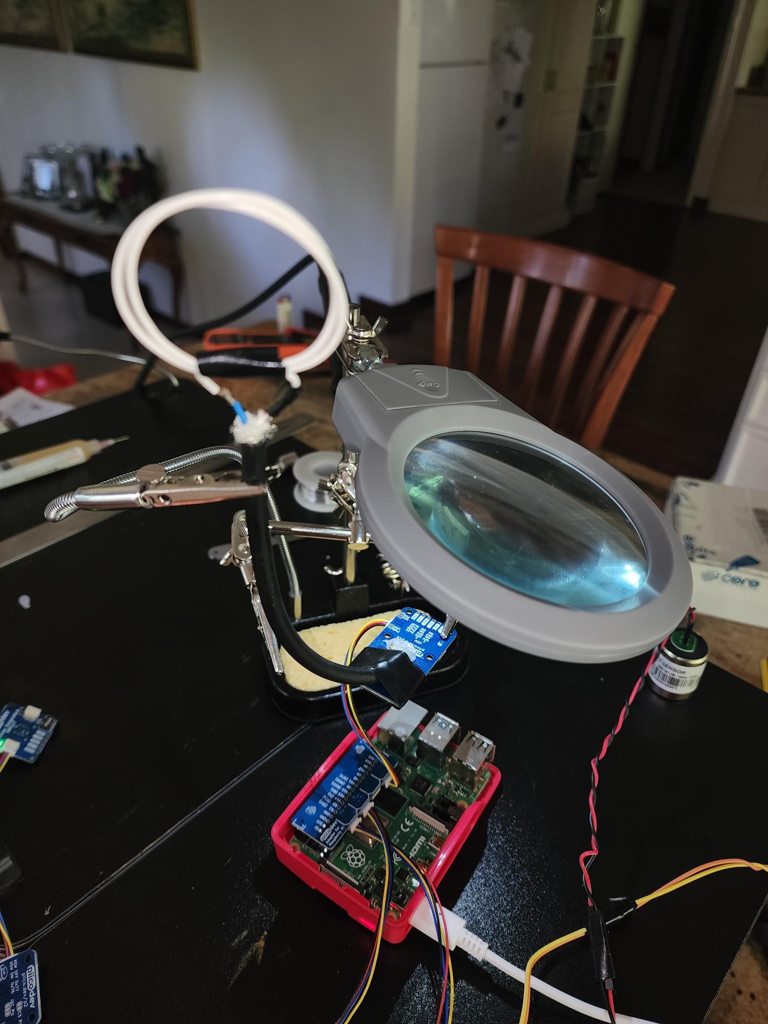
Images for reference (please excuse my terrible soldering. And yes, I will use heat shrink on those terminals for when I make the real version):
Sweet work on extending that antenna!
Disclaimer, I have not studied RF Engineering so all of what I’m about to say has been passed on from countless hours of YouTube and reading.
What kind of range are you hoping to get?
The datasheet for the IC lists a maximum range of 50mm
Yeah, the antenna is currently adding impedance, cutting just behind where you soldered the new antenna should reduce the overall impedance (more on this later)
Its really hard to say, whire length isnt the only thing that affects how an antenna performs!
A VNA is used to test the characteristics of an antenna so without one its super hard to say: 1. Network Analyzers | Keysight.
(Its also not just the boards settings, the radio amplifier onboard expects an impedance, a lot of this is in the antenna but a matching network is often needed as well)
Unfortunately its hard to say for either of these
Not in the driver from the looks of it, there seem to be some other registers that can be set to change the minimum RSSI from a tag to get a proper read but these dont seem to be set
The read distance only needs to go up by a few cm, 50mm would be incredible if I could achieve it, but realistically 40mm or even 30mm would do.
Easy done. I was almost certain this was the case, but didn’t want to damage the original trace unless it was likely to make a difference.
Hmmmm, I wonder if I could jimmy one up using an SDR. I ran a RPi controlled ADS-B a couple of years back, and the Flight Aware’s RTL-SDR was more than capable of picking up NFC frequencies. Could be a good way to consistently measure the chatter between the tag and the reader across different settings. Food for thought!
That actually could be a good option! I don’t actually need to read the tag ID, just check if there’s one there. I’ll try and find out myself, but from your knowledge, does the .tagPresent() and .readID() calls have different thresholds for success? I imagine that detecting a return signal vs. actually pulling data from the signal are quite different in terms of minimum RSSI.
It’s a complicated scenario, but in essence I’m tagging an object moving through hole in a brick wall (~3.5 cm diameter), and I want to detect that object as it approaches the end of the hole. All I need to do is know when it approaches the antenna (Attached to the outside of the wall around the hole). That’s why I needed the external antenna, so the object can pass through the ‘eye’ of the coils unimpeded, but I can tell when it does, OR if it moves close to the hole, but doesn’t come out/returns back (I don’t need to distinguish between these two scenarios). The hole is capped with a hinged lid so I can’t see inside the hole (Otherwise I’d use LiDAR or similar). Sounds strange I know, but there’s method to my madness!
Wow! What a project idea you have here. I think its awesome that you are using this for such an awesome purpose in this project and it is a great way of using RFID in a different but useful way.
Have you been having any issues getting a reading on these NFC chips as they pass through? The question I would pose is if it is better to use this in a sense of if power is being drawn rather than if there is an active tag in range. As RFID tags interact they are drawing power to output their signal and that slight power drop may be a faster and more effective way of reading the chips presence if there isn’t a need to read the tags themselves.
I would love to see where this project progresses, it really embodies the maker spirit of using something in a different way and making it the most effective tool for the job!
Hi Blayden,
The only nfc chips I have lying around at the moment are built into cards (my standalone chips are still on their way. I ordered 5mm x 5mm nfc tags from America), so I can’t test it going through until they arrive, but at the very least, I can read the card at a distance of 20ish mm.
How would I measure the power drop? I didn’t think the pi could measure its draw out of the box? Also I have several other devices on the I2C so the voltage on the power is going to be pretty variable! Does the RFID board keep track of its draw, or would I need to hook up a current sensor (Like SEN-13679) on the power line between the piicodev adapter and the rfid board?
I did some investigating around that register (RxThresholdReg).
When I run this on my terminal i2cget 1 0x2c 0x18
I get 0x42
Which to me implies the MinLevel and the CollLevel are both set to 2 (Assuming the bit order is 7 to 0, and the individual values are MSB first). The data sheet doesn’t really go into how that is meant to work, but I’m considering setting this register to 0x00 to remove any threshold at all.
Does this sound reasonable?
Thanks again,
Cam
[UPDATE 1]:
Setting the register to low values reduced the read range (with 0 making it essentially ‘off’). By setting it to 239 (Which just floods both values with 1’s), there was maybe a few mm increase in detection distance.
For anyone else trying this, the initialisation command in python calls a soft reset of the board, which resets the register back to the default 0x42. To enforce this setting, you need to assign to your register immediately after your initialise, which for the RFID board can be done with:
reg_address_as_decimal = 24
new_reg_value_as_decimal = 239
rfid = PiicoDev_RFID()
rfid.i2c.writeto_mem(rfid.address,reg_address_as_decimal,bytes([new_reg_value_as_decimal]))
I have no idea of the risks of doing this, so please be careful and make sure to read the manual.
[UPDATE 2]:
Also found the receiver gain register (RFCfgReg), and managed to modify it to 0x7F (as per this C++ arduino discussion using the same chip). When I initially read this register (i2cget 1 0x2c 0x26) it gave a value of 0x44 which is unusual, because that places a 1 in the reserved bits. The C++ implementation also seemed to set bits in the reverse order, but nothing worked until I plonked in 0x7F. This gain value gave me a solid 10mm extra, bringing the final read distance of my custom (and dodgy) antenna to a whopping 70mm (Presence/Absence - Haven’t tried to read tag values). From incrementally changing things, I think I got a read distance advantage from the following:
Original antenna: 25 mm
Cutting the existing on-board antenna traces: +30 mm
This is incredible detective work @ProgrammerScum - thanks for taking the time to share your progress and document your work! This is what open source is all about Consider baking your work into a Pull Request on the repo (and don’t forget to include docs in the README.md) - Rx thresholds seems like a useful parameter for the user to be able to set. Starting off with a conservative value is always good, to guarantee success. But who are we to stand in the way of a user wanting to squeeze every millimeter possible out of their device like you have
I’m hoping the process is useful for someone else, because in the end I couldn’t use it for my project! The trouble I’ve found is that although the reader works at 7cm with the nfc tag in my phone, it can’t read the 5mm x 5mm nfc tags I ordered, unless the tags are touching the aerial (At this stage likely due to the tag’s aerial being so much smaller, and that the phone uses an active tag).
I switched to using power draw like @Blayden suggested, but the power draw was only 0.1 to 0.2 mA (Read using a multimeter inline on the CE08086’s red/3.3V wire) when reading, and when idle (No tag present) the value often drifted up to ±1 mA. I may have read the data sheet wrong, but I believe that’s outside the sensitivity of the SEN-13679 by two orders of magnitude.
Things I’m yet to try:
Test current draw on antenna itself, not just on the power line for the CE08086
Test my new tags on a unadulterated CE08086 to see if its my antenna that’s causing the problem
Order the substantially more expensive RFID board (Which has an external antenna) from the company who made the nfc chips I’m using.
Lots to try to salvage this project. I’m hoping its just my terrible antenna that’s causing the problem, because my project requires the nfc tags to be at least that small.