Hey, I recently bought the rotary encoder with button, the knob was working fine before but now it won’t output anything, the button is fine though

1 Like
Hi Sebastian,
Welcome to the forum!!
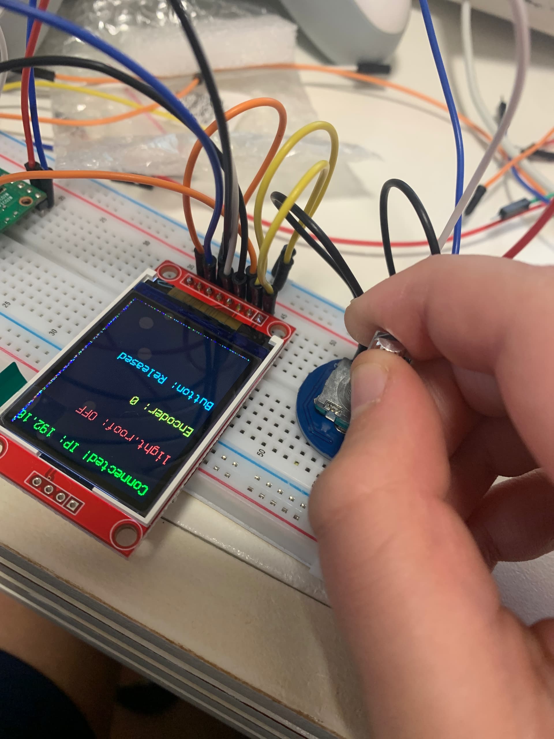
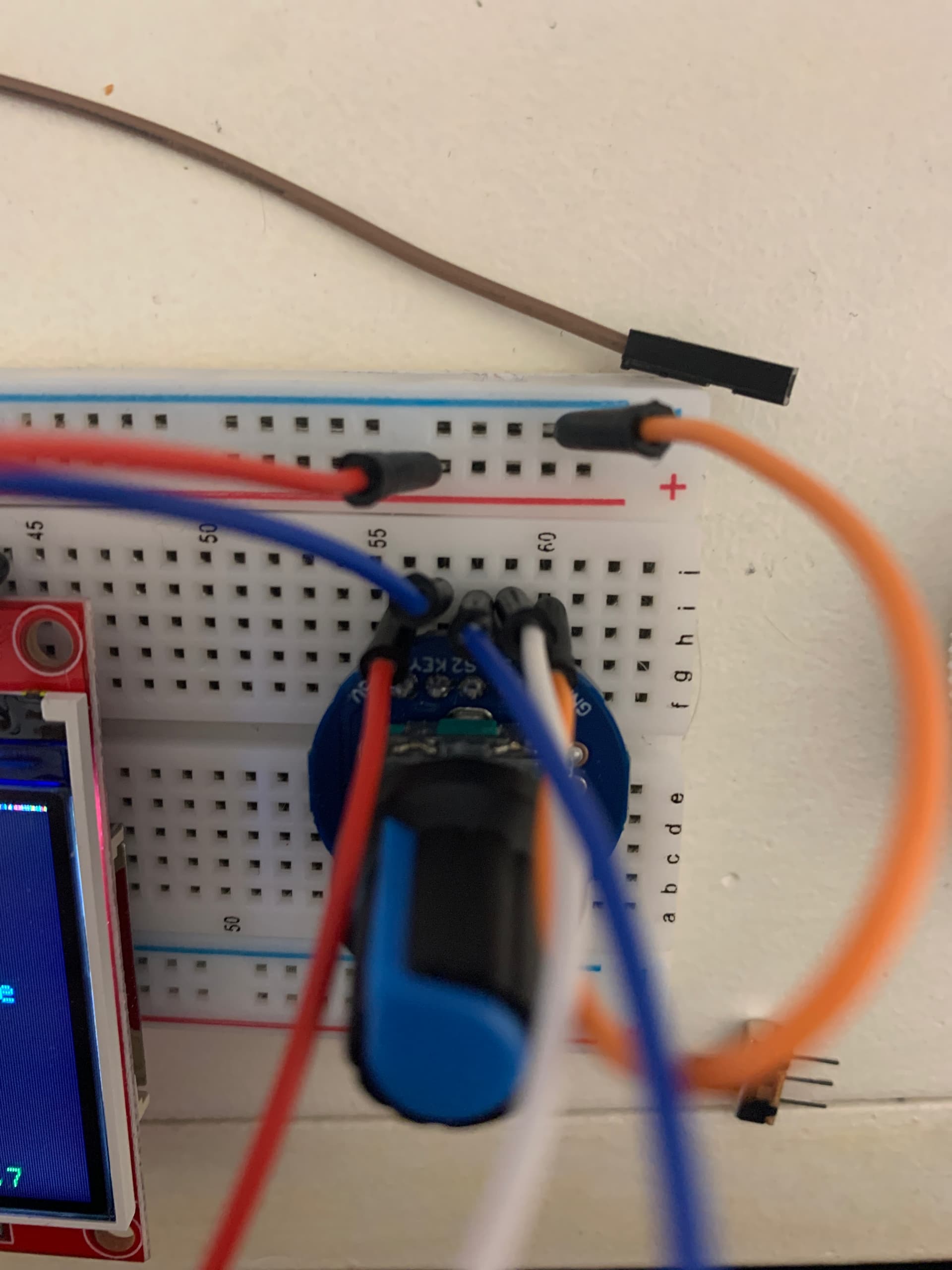
Would it be possible to remove your finger from the frame? It looks like there are only 4 wires going to the module, for the encoder and button to work you’ll need 5 (encoder_a, encoder_b, and the button)
Sending through your code and links to tutorials you are following will help the community debug.
Liam
1 Like
Hey Liam! Here is the photo of the rotary encoder, I don’t know, but it’s probably fried (I’m a rookie maker) still, no rotation input, but there is button input
I’ve come to a conclusion that the encoder is fried, I think I know how I did it too… I might have once accidentally put 3.3 volts into s1 once gulp
Hi Sebastian
A hell of a lot more info here please. The photos mean absolutely nothing.
Exactly what is that encoder module you are using. The only way you would “fry” the encoder is to weld the switch contacts. One module sold by Core has on board filters and pull ups, the switches are supplied via 10k ohm resistors which isn’t going to “fry” anything.
A schematic of some sort showing how all this is connected and where you are monitoring encoder switch action please.
Cheers Bob
Hi robert! i wouldnt know how to make a schematic Encoder Module with button | Buy in Australia | CE09436 | Core Electronics this is the module, im kinda new to this sorta stuff so i wouldnt know that much
Hi Sebastian
That encoder I think (according to the text) has the filters and pull ups on board. I would not personally be able to check the arrangement until I get home next week.
Correction here. I just had another look at the product and it is indeed the one I suspect.
Please go to the product page (click on your own link) and look under “Comments”. You will find the whole previous thread and a schematic of this board. I think you should read this. The encoder switches switch the A and B to ground when they operate. Pull up resistors to 5V (or 3V3) of 10k are on this board.
If your expertise does not stretch to a “proper” schematic can you do some sort of diagram showing hew everything is connected. This would be a big help.
Cheers Bob
ok i so pasted in the schematic and gemini (oh god i love gemini) fixed my code for it to work
Hi Sebastian
So, all good now ???
Cheers Bob
1 Like
Yeah, works well
1 Like