This is a placeholder topic for “Schottky Diode” comments.

Schottky diodes are known for their low forward voltage drop and a very fast switching action. This 1A 40V Schottky diode is ideal for use with motor drivers such as the L298N.
Read moreThis is a placeholder topic for “Schottky Diode” comments.
Schottky diodes are known for their low forward voltage drop and a very fast switching action. This 1A 40V Schottky diode is ideal for use with motor drivers such as the L298N.
Read moremany of the diodes listed don’t include the device number, eg 1N5819. The data sheet is for 5817,5818,5819 so we cannot tell which one you are selling ![]()
Hi Steven and all
A very valid point which would do well to be corrected along with some other offerings.
You can find out by looking at the Data sheet and remembering the “40V” bit of the description.
Thus this device is 1N5819 if you can believe the description which is probably a verbatim copy of the supplier’s text. Without any attempt at proof reading or editing. Happens quite often.
The Data sheet. That is something else again. About as skinny as I have seen.
Be aware the reverse leakage current for some of these devices can be quite high. This one is quoted as 1mA @ rated reverse voltage. This would make them quite useless where leakage needs to be kept at a minimum like in the nA or pA range.
Cheers Bob
Hey there, @Steven15255,
Sorry about that. I can confirm that we are currently selling the 1N5819 variant.
As Bob said, you can always crosscheck with the datasheet and the voltage, but even so I’ll go ahead and update the webpage to be more clear for the future.
No worries, thanks for that.
I decided not to buy one of these after all – Bob’s point about the leakage current was useful – I needed uA leakage rather than mA leakage to protect a tiny 5.5mAh cell from being drained.
In the end I had to buy a surface mount diode and suffer the high shipping cost!
Hi Steven
Another thing to know about diodes, particularly the glass type. All PN junctions will respond to light. Some quite badly. Even the common 1N4148. The difference in leakage between being in darkness and full daylight is staggering. Mostly they are bottled up and in full darkness as in daylight the leakage can be several hundred µA..
So if you are twitchy about leakage you would do well to remember this. You could cover the diode with a very small bit of black heat shrink but be careful not to let it touch the wires or you have another leakage path.
Actually “back in the day” when diodes and transistors were painted black and you wanted a photo diode or photo transistor you just scraped some of the paint off and you had it.
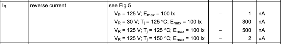
I was looking into some low leakage diodes for another project some time ago and I found a few that actually quoted the light level the data sheet figures were taken.
Actually if you are interested you can easily measure this leakage down to nanoA.
Get a convenient voltage, 10 V makes it easy. Connect positive to diode cathode. Connect pos of DMM to diode anode. connect neg of DMM to 10V neg. DMM set to read volts.
What you see is the voltage drop caused by the leakage current across the 10MΩ of the DMM.
Using 10V this equates DMM = 1V leakage is 0.1µA or 100nA. So you see it is quite easy to measure right down to a few nA using this method.
Interestingl experiment.
Cheers Bob
PS keep your fingers off or you could read anything.
Add on:
Part of data sheet for BAS45A low leakage diode.
Thanks again Bob, that’s a very useful to know test for leakage, and the light sensitivity too.
Learned two things today!
Regards, Steve
Hi Steven
Regarding that leakage test I described. If you try this DO NOT plug the bits into a breadboard. If the breadboard has any age to it (like getting old) the leakage here is likely to be worse than any diode. Regardless of age these things have their share of stray Capacitance and Inductance which can be embarrassing at times and lead to lots of false funnies
For an example. Some time ago I was playing around with a 555 in astable mode. My timing calc were a bit off. I found the 555 oscillated quite happily with NO timing cap fitted. From the frequency generated I estimated the stray cap to be about 50pF.
Something to keep in mind when using these boards.
Cheers Bob
And you can get our latest projects and tips straight away by following us on:
![]()
![]()
![]()
![]()