Hi John,
What a sweet enclosure!
What printer did you use to make this?
The parametric-ness of OpenSCAD is really something - I’ve really got to dip my toes in, but Fusion for work and OnShape for hobby projects is just such an easy combo.
I wanted to see and appreciate the programmatic → 3D goodness so had a look at the file (and thought it would be kind to share).
Johns work not mine…
/*
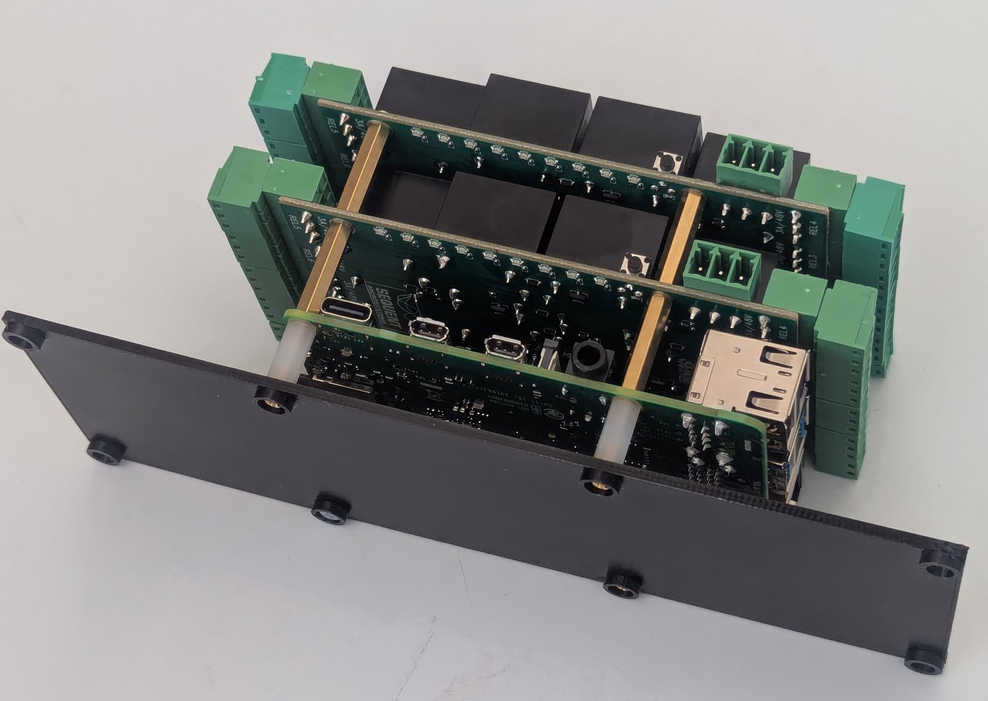
OpenSCAD design to produce enclosures for Pi and 1 to 8 Sequent
8 channel relay boards.
There is a base for attaching to the Pi after the relay boards
have been attached to the Pi. This base can be screwed to a bench.
There are 2 side boards that slot into the Pi base (under and over)
and a lid that screws to the side boards
To use set num_relay_boards then go to the end and enable each of
the commented out calls in turn to produce the four STL files.
*/
$fn=120;
// Change this parameter to a value between 1 and 8 according to the number
// of relay boards used
num_relay_boards = 2;
// Pi 4 dimensions. Should be the same for Pi 5
pi_width = 85 + 4;
pi_lng = 56;
hole2hole_y = 58;
hole_y_1_offset = 3.5;
hole2hole_x = 49;
// Measurements for a base
part_thick = 2;
hole_dia = 3.2;
screwhead_dia = 5;
standoff_dia = 7;
// The base needs to be extended to suit relay connectors and allow
// screwdriver access to screw holes to fasten base to a bench
sd_card_end_extra = 35 + 12;
usb_end_extra = 20 + 12;
screwdown_dia = 4.5;
// Stand-offs are supplied with the relay boards. However 4 12 mm
// 2 mm female to female stand-offs are also required. These screw on
// under the Pi to the male ends of the bottom relay board stand-offs.
// The underside of the base has stand-offs that allow 2 mm dia screws
// to connect the 12 mm stand-offs with the screw head recessed.
pi_stand_off = 12;
pi_base_thick = 1.5;
relay_base_thick = 1.65;
relay_standoff = 19;
clrc = 0.75;
sidewidth = pi_width + sd_card_end_extra + usb_end_extra;
// There are 2 side plates that fit over the base plate and are held in
// place by a lid that is fastened to stand-offs by self tapper screws.
// The side height depends on the number of relay boards
sidehgt = 2*part_thick + pi_stand_off + pi_base_thick
+ (num_relay_boards + 1) * (relay_base_thick + relay_standoff)
+ 5; // Extra clearance //85;
// Provide clearance between Pi and side for ventilation and a 90 degree
// USB power cable
side_clrc = 20;
// Set the width that suits slotting the side to the base
overlap = 32;
// Connect top to sides using M4 self tapper screws
screw_dia = 3.5;
screw_column_dia = 8.5; // Stand-offs to fasten lid
module pirelayboxbase(){
difference(){
union(){
// Pi footprint
translate([-pi_lng/2, 0, 0]){
cube([pi_lng, pi_width, part_thick]);
}
// Add overlaps for relay hats and securing holes
translate([-pi_lng/2, -sd_card_end_extra, 0]){
cube([pi_lng, sd_card_end_extra, part_thick]);
}
translate([-pi_lng/2, pi_width, 0]){
cube([pi_lng, usb_end_extra, part_thick]);
}
// Base to bench screw down offsets
translate([-hole2hole_x/2, -sd_card_end_extra + standoff_dia/2, 0]){
cylinder(h=2*part_thick, d=standoff_dia);
}
translate([hole2hole_x/2, -sd_card_end_extra + standoff_dia/2, 0]){
cylinder(h=2*part_thick, d=standoff_dia);
}
translate([-hole2hole_x/2, pi_width + usb_end_extra - standoff_dia/2, 0]){
cylinder(h=2*part_thick, d=standoff_dia);
}
translate([hole2hole_x/2, pi_width + usb_end_extra - standoff_dia/2, 0]){
cylinder(h=2*part_thick, d=standoff_dia);
}
// Pi Standoffs
translate([-hole2hole_x/2, hole_y_1_offset, 0]){
cylinder(h=2*part_thick, d=standoff_dia);
}
translate([hole2hole_x/2, hole_y_1_offset, 0]){
cylinder(h=2*part_thick, d=standoff_dia);
}
translate([-hole2hole_x/2, hole_y_1_offset + hole2hole_y, 0]){
cylinder(h=2*part_thick, d=standoff_dia);
}
translate([hole2hole_x/2, hole_y_1_offset + hole2hole_y, 0]){
cylinder(h=2*part_thick, d=standoff_dia);
}
} // Union
// Screw holes to connect Pi base to a bench
translate([-hole2hole_x/2, hole_y_1_offset, 0]){
cylinder(h=20, d=hole_dia);
}
translate([hole2hole_x/2, hole_y_1_offset, 0]){
cylinder(h=20, d=hole_dia);
}
translate([-hole2hole_x/2, hole_y_1_offset + hole2hole_y, 0]){
cylinder(h=20, d=hole_dia);
}
translate([hole2hole_x/2, hole_y_1_offset + hole2hole_y, 0]){
cylinder(h=20, d=hole_dia);
}
// Screw head holes to connect Pi base with heads recessed
translate([-hole2hole_x/2, hole_y_1_offset, part_thick]){
cylinder(h=20, d=screwhead_dia);
}
translate([hole2hole_x/2, hole_y_1_offset, part_thick]){
cylinder(h=20, d=screwhead_dia);
}
translate([-hole2hole_x/2, hole_y_1_offset + hole2hole_y, part_thick]){
cylinder(h=20, d=screwhead_dia);
}
translate([hole2hole_x/2, hole_y_1_offset + hole2hole_y, part_thick]){
cylinder(h=20, d=screwhead_dia);
}
// Screw holes to attach to bench
translate([-hole2hole_x/2, -sd_card_end_extra + standoff_dia/2, 0]){
cylinder(h=20, d=screwdown_dia);
}
translate([hole2hole_x/2, -sd_card_end_extra + standoff_dia/2, 0]){
cylinder(h=20, d=screwdown_dia);
}
translate([-hole2hole_x/2, pi_width + usb_end_extra - standoff_dia/2, 0]){
cylinder(h=20, d=screwdown_dia);
}
translate([hole2hole_x/2, pi_width + usb_end_extra - standoff_dia/2, 0]){
cylinder(h=20, d=screwdown_dia);
}
} // Difference
}
module pirelayboxside(){
difference(){
union(){
// Under base
translate([pi_lng/2 - overlap + side_clrc, -sd_card_end_extra, part_thick]){
cube([overlap, sidewidth, part_thick]);
}
// Over base
translate([pi_lng/2 - overlap + side_clrc, -sd_card_end_extra, - part_thick - 0.17]){
cube([overlap, sidewidth, part_thick]);
}
// Side
translate([pi_lng/2 + side_clrc, -sd_card_end_extra, 2*part_thick - sidehgt]){
cube([part_thick, sidewidth, sidehgt]);
}
// Lid screws supports
translate([pi_lng/2 + side_clrc - screw_column_dia/2 + part_thick, 0, 2*part_thick - sidehgt]){
cylinder(h=sidehgt, d=screw_column_dia);
}
translate([pi_lng/2 + side_clrc - screw_column_dia/2 + part_thick, pi_width, 2*part_thick - sidehgt]){
cylinder(h=sidehgt, d=screw_column_dia);
}
} // Union
// Cut-outs for stand-offset
hull(){
translate([-hole2hole_x/2, -sd_card_end_extra + standoff_dia/2, -10]){
cylinder(h=20, d=standoff_dia + clrc);
}
translate([hole2hole_x/2, -sd_card_end_extra + standoff_dia/2, -10]){
cylinder(h=20, d=standoff_dia + clrc);
}
}
hull(){
translate([-hole2hole_x/2, pi_width + usb_end_extra - standoff_dia/2, -10]){
cylinder(h=20, d=standoff_dia + clrc);
}
translate([hole2hole_x/2, pi_width + usb_end_extra - standoff_dia/2, -10]){
cylinder(h=20, d=standoff_dia + clrc);
}
}
// Pi Standoffs
hull(){
translate([-hole2hole_x/2, hole_y_1_offset, -10]){
cylinder(h=20, d=standoff_dia + clrc);
}
translate([hole2hole_x/2, hole_y_1_offset, -10]){
cylinder(h=20, d=standoff_dia + clrc);
}
}
hull(){
translate([-hole2hole_x/2, hole_y_1_offset + hole2hole_y, -10]){
cylinder(h=20, d=standoff_dia + clrc);
}
translate([hole2hole_x/2, hole_y_1_offset + hole2hole_y, -10]){
cylinder(h=20, d=standoff_dia + clrc);
}
}
// Top screw holes
translate([pi_lng/2 + side_clrc - screw_column_dia/2 + part_thick, 0, 2*part_thick - sidehgt]){
cylinder(h=30, d=screw_dia);
}
translate([pi_lng/2 + side_clrc - screw_column_dia/2 + part_thick, pi_width, 2*part_thick - sidehgt]){
cylinder(h=30, d=screw_dia);
}
} // Difference
}
module pirelayboxsidemirrored(){
mirror([1,0,0]){
pirelayboxside();
}
}
module pirelayboxtop(){
difference(){
union(){
// Main top part
translate([-pi_lng/2 - side_clrc - 2*part_thick, -screw_column_dia/2, part_thick - sidehgt]){
cube([pi_lng + 2* side_clrc + 4*part_thick, pi_width + screw_column_dia, part_thick]);
}
// Outer sides
translate([-pi_lng/2 - side_clrc - 2*part_thick, -screw_column_dia/2, part_thick - sidehgt]){
cube([part_thick, pi_width + screw_column_dia, 4*part_thick]);
}
translate([pi_lng/2 + side_clrc + part_thick, -screw_column_dia/2, part_thick - sidehgt]){
cube([part_thick, pi_width + screw_column_dia, 4*part_thick]);
}
// Inner sides
translate([-pi_lng/2 - side_clrc + 0.2, (1.5*screw_column_dia)/2, part_thick - sidehgt]){
cube([part_thick, pi_width - 1.5 * screw_column_dia - 2, 4*part_thick]);
}
translate([pi_lng/2 + side_clrc - 0.2 - part_thick, (1.5*screw_column_dia)/2, part_thick - sidehgt]){
cube([part_thick, pi_width - 1.5 * screw_column_dia - 2, 4*part_thick]);
}
} // Union
// Screw holes
translate([pi_lng/2 + side_clrc - screw_column_dia/2 + part_thick, 0, 0]){
cylinder(h=300, d=screw_dia, center=true);
}
translate([pi_lng/2 + side_clrc - screw_column_dia/2 + part_thick, pi_width, 0]){
cylinder(h=300, d=screw_dia, center=true);
}
mirror([1,0,0]){
translate([pi_lng/2 + side_clrc - screw_column_dia/2 + part_thick, 0, 0]){
cylinder(h=300, d=screw_dia, center=true);
}
translate([pi_lng/2 + side_clrc - screw_column_dia/2 + part_thick, pi_width, 0]){
cylinder(h=300, d=screw_dia, center=true);
}
}
} // Difference
}
// Enable each of the following in turn to create the 4 STL files required.
//pirelayboxbase();
//pirelayboxside();
//pirelayboxsidemirrored();
//pirelayboxtop();
Liam