I’m very much a programming rookie, but I’ve been tasked with sniffing and interpreting data sent from a scoreboard controller to the scoreboard itself over a 2 wire RS-485 connection. I’ve used a (cheap) RS-485 to IP converter, but I’m having no luck receiving useable data, or even transmissions that could even be seen to sync with the time data being sent across the connection.
Is there anyone here in the Newcastle/Lake Macquarie area who would be able\interested in assisting on this project, or who could start pointing me in the correct direction?
Hi Michael
RS485 is only the transport medium. With some speed and load limitations it will take anything you give it and transport this information to an end (and intermediate) devices to interpret and use.
Just connect another RS485 device across the line and it should output whatever goes in. The “A” and “B” line must be identified and connected correctly, A to A and B to B.
This system requires terminating resistors (120Ω) at each end of the line. 2 wire suggests one way traffic or half duplex. One way requires 120Ω at the receive end only while half duplex requires 120Ω at each end. This termination MUST NOT BE USED on intermediate devices.If it has this fitted it MUST be removed. Easy to establish, measure the resistance between A and B. Open circuit is OK, if 120Ω measured the resistor must be removed (may be a solder bridge or link) or this unit cannot be used as an intermediate device.
Some devices also have a resistor fitted between A and Positive power and B and negative power. I would advise removing these also. Do all these resistance measured with the device UNPOWERED.
Don’t forget the intermediate device will see traffic in both directions (if half duplex)
Add on.
DO NOT connect intermediate devices with another length of cable connected to the main feed. The intermediate devices MUST be connected directly to the main cable then the cable carries on to the end destination. You MUST NOT have odd lengths of cable hanging off the main cable run.
Cheers Bob
This device USB Logic Analyzer - 24MHz/8-Channel | Sparkfun TOL-18627 | Core Electronics Australia (core-electronics.com.au)
is a simple and inexpensive way to tap into any serial communication link and analyze the data. It is designed for TTL voltage levels, so you may need a level shifter (such as a divider network). The particular advantage of this product is that the software that runs on the PC includes a huge range of serial data protocol analyzers, and there is a good chance that there is one that can interpret the scoreboard data. If the data format is unknown you will still be able see the bit pattern so you can match it to the known data values.
This is a strange one (in my uneducated opinion) - it’s all connected using RJ45 connectors. A single RJ45 TP cable runs from the back of the scoreboard controller into a splitter, and then from the splitter, RJ45 TP cables run to both a primary scoreboard and an auxiliary scoreboard at the other end of the stadium. I’ve identified the A & B wires, but I’m having a hard time working out the baud, bit count, and the other variables in order to read the data. As I said - rookie, haha. I’ve not really got an idea as to whether the stuff I’m reading means anything, but there doesn’t seem to be a rhyme or reason to the data.
I’ve spoken to the original manufacturer, but because this system was developed so long ago, they don’t have any design documents on file to assist with reverse engineering, which really sucks.
I’d love to find an expert and hire them to take a look and design a solution, but I don’t even know where to look for someone with that skill set, so I figured starting in this community was appropriate.
This looks awesome, and relatively inexpensive. Perhaps this is the missing piece I need to work out whether I’m getting junk or good data. This is only one piece of the puzzle though - once I’ve found the data, I will then need to have something to interpret said data and output it to XML in a specific format - something I’m sure can be achieved via arduino or Rpi. All of this consists of skills I’d love to learn, but are currently beyond me.
It depends on the logic analyzer, but most can export to an XML or CSV file, I wouldn’t worry about a separate datalogger project unless you find your LA can’t do this
Not so strange. In essence an RS485 cable run must only have 2 ends, no bits of cable splitting off somewhere otherwise reflected signals off any odd bits will play merry hell with wanted data on the line.
This sounds like a dedicated system design. Could be one of two things.
The “splitter” at the controller is active and you have in effect 2 RS485 runs. OR
The “ends” are at the 2 scoreboards and the controller connection is actually an intermediate device (unterminated). All end and intermediate devices can be the same, the only difference is the presence or not of a terminating resistor.
All devices “see” the information on a line so the scenario of option 2) is viable.
The comments about connecting another intermediate device to “sniff” the data still stand. NO odd lengths of cable hanging off the mail line. The actual mechanics of this will depend on the actual installation and where you need to monitor.
You could even remove the termination from one scoreboard and continue the cable run to your sniffer position and because this will be a cable end terminate (120Ω) at this point.
I am stressing here that terminations must be at cable ENDS to stop reflections corrupting data signals.
Cheers Bob
The application does the interpreting, unless it’s a very unusual format. You will get a clue about what the format is likely to be by looking at the devices that are used for creating and displaying the data. For instance, if there is a generic MCU at the display board end then it’s likely that the data is something simple like ASCII and the MCU is interpreting it for the display. But if the connection is directly into a display module, then the format might be some form of image data and that’s going to be a lot more difficult. Similar examination at the input end will suggest how the data is being encoded for transmission.
The logic analyzer software allows for export as raw binary data or decoded ASCII (CSV, or HEX stream, provided, of course, that the format is one that it can decode).
I am in the same stuff currently. Did you made any progress? Can you name the MFG of the scoreboard, ours is from Westerstrand, Sweden. It uses a RS485 protocoll but I cannot figure out the commands. Would like to all infos you collected. Thanks in advance.
(Not the same op michael)
I would think from what I think you are looking at, is a simple logic analyzer and sample both the signal lines. From there you should be able to work out the UART Settings that feed the line drivers.
Once you have that tuned in, you could either just used the logic analyzer to work out the commands (.i.e. drop the start/stop/parity and just get the raw command/responses).
Once you know that, you should be able to inject as needed and/or write the code for a sniffer device if that is your end goal.
If you want to jump directly into sniffing, then you will need to know the com port settings; baud parity stopbits etc. If you know that, then an RS485 to Serial conencted to a PC would get you the data.
Keep in mind, there is no reason that the data cant be binary data. This is also no reason why they could not encrypt it at a higher level (but they may not).
this one will work fine and you can use the free pulseview software.
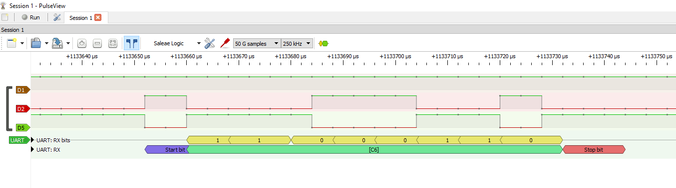
Just to add a little.
With the above logic analyzer and pulse view connected to an RS485 transmitter.
I added the UART decoder, worked out the baud rate and tweaked the invert bits till I got a good looking decode.
I might be able to point you in the right direction. RS-485 sniffing can be a bit tricky, especially with cheap converters, because many of them don’t properly handle differential signaling or timing. To reliably capture the scoreboard controller data, you’ll usually need an RS-485 adapter that supports true 2-wire half-duplex and lets you monitor raw frames without filtering.
Also, some scoreboards use proprietary or non-standard protocols, so the data may not look like readable ASCII—you may see binary bytes, sync pulses, or repeating frames. A logic analyzer with RS-485 input, or a quality USB-to-RS-485 interface, can make a big difference.
I’m not in the Newcastle/Lake Macquarie area, but if you’d like, I can help guide you through the setup, mini Laser Transmitter KY-008 testing or interpreting the raw data. If you can share a short capture (hex or raw), I can help figure out what protocol the scoreboard is using.