I’m dancing around lot’s of different motors at the moment.
I’ve got an ESP32 and I have the simple goal of motor goes to the position of a potentiometer.
#include <ESP32Servo.h>

Servo myservo;
int servoPin = 4;
int potPin = A0;
int ADC_Max = 4096;
int val;

void setup()
{
  pinMode(LED_BUILTIN, OUTPUT);
  pinMode(potPin, INPUT);
  pinMode(servoPin, OUTPUT);
	ESP32PWM::allocateTimer(0);
	ESP32PWM::allocateTimer(1);
	ESP32PWM::allocateTimer(2);
	ESP32PWM::allocateTimer(3);
  myservo.setPeriodHertz(50);
  myservo.attach(servoPin, 500, 2400);
}

void loop() {
  digitalWrite(LED_BUILTIN, HIGH); //I'm doing something
  val = analogRead(potPin);
  val = map(val, 0, ADC_Max, 0, 180);
  myservo.write(val);
  delay(200);
  digitalWrite(LED_BUILTIN, LOW); //I did it!
  delay(200);
}
No movement, but I am getting the led on pin 4 to flicker… but real slow.
I can tell you it works but only if I use my Arduino Leonardo and the servo library.
If you take out the LED does it give you any better results? Could be that the LED is drawing too much current on that pin to both drive the signal for the servo and the LED.
The code looks good, and I’ve checked all the connections, strange. I suspect that the serial print will reveal the issue once you can get it working. Let us know how it goes!
Have you confirmed that the serial is connecting when the XIAO is isolated (i.e. taken out of the breadboard)? That should be a pretty easy way to tell if there’s some sort of issue with the circuit itself.
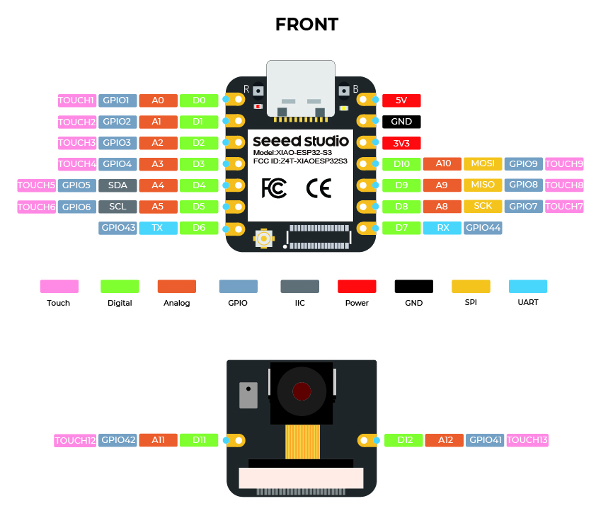
Notice the Xiao’s pinout is zero indexed.
Arduino IDE, however, must NOT be zero indexed!
i.e.
const int D0 = 1;
const int TX = 7;
const int RX = 8;
So my bug was here:
int servoPin = 4; // Pin4 is D3 on the Pinout diagram.
Solved by moving my green PWM wire across to D3.
My oscilloscope is the best a bijillion dollars I e’er spent.
P.S.
I resolved my zero feedback from the serial monitor issue by sys-killing my computers lock on the Serial Port via terminal. That while(!Serial) {} was causing the Xiao to hang, waiting for a connection that would never be released.