Hello,
I am powering 2 telescope systems via a 12 volt rail. Now what I want to achieve is too sense the load on each split rail and light up a LEDs on the relevant rail. Initially I thought the ACS723 board might do the job but not sure.
As I have some TIP3055 NPN transistors lying around my first thought was using these on the GND side, but as I don’t want to put the load which may be in the order of 2-5 amps, through to the base to enable the switching I would appreciate some assistance as the best way to proceed.
Hi Jim
The 3055 is a pretty beefy transistor. Bit of an overkill to switch a LED at about 10mA.
You would not do this to switch a transistor .
Have you got a bit of a circuit showing what you are trying to achieve. Are you just indicating when the particular telescope is switched on or are you needing to indicate when the telescope is actually drawing current. If the latter that sensor will certainly do the job and it would only remain to devise a means for that to switch a LED. The only downside would be you would have to arrange 5V for VCC.
Cheers Bob
Thanks Bob,
Getting 5V per split rail is not an issue as I have some LM2596 boards on hand. They can take the 12V coming in and be adjusted to put 5V out to the sensor boards.
As to switching the LED and correct me if I am wrong the VOUT of that board supplies a voltage out that I could use with a limiting resistor to power the LED.
I believe I was talking to you on the online chat about this one.
Here’s where we got up to for others following along:
I liked the idea of directly driving an LED from the ACS723, but its datasheet doesn’t give specs on how much current it can sink/source, so I’m not sure how it will go driving the LED. It also lists an “Output Resistive Load” of 4.7K. Not sure what that means in the context of LED driving, so maybe someone can chime in here with their thoughts?
This is a really cool simple project that I haven’t seen before, so I’m keen to get to the bottom of it
-James
It means it has a source capability of about 0.5mA. That is 2.5V divided by 4k7. Not enough to drive a LED. It also means that any base resistor used needs to be minimum 4k7 because if a transistor is used as a low side switch the base will be 0.6V above ground. This however is not exactly how you would switch a transistor as the current sensor starts at VCC/2 or 2.5V at VCC 5V so the emitter would have to connect to an artificial ground such as VCC/2 as used in some audio circuits.
Far easier to use something like LM393 dual comparator set for a reference of just above VCC/2 and these have a very handy open collector output. Just connect the sensor output (via a series resistor) to the inverting input and the LED with a current limiting resistor from VCC or other source (with open collector output this is isolated). This output is capable of 20mA so select resistor for 10mA and all will be OK. When the LM393 input goes above the reference the comparator will switch and the output will go LOW, that is the output transistor will switch on.
Hello all,
I have found a small pre-made board which should do the job. That said I also grabbed some LM393’s to play with and see if I can emulate what this board does. As it is from another supplier I will not mention any more details on it unless that is AOK with Core Electronics.
Will update this with how I go and anything more accordingly.
Thanks for the helpful comments.
Jim
Hi James
LM393 is a dual comparator with an open collector output (analog ???) so it looks as if Jim is going to experiment along the lines I suggested.
Jim. Did a bit of math for your reference. 9k1 and 10k in series with the 10k on the ground side will put your reference at a bit more than 100mV above VCC/2. This should equate to switch on at about 250mA to 300mA through your sensor. Both resistors are preferred values in 1% range and readily available. Connect the non inverting inputs from the resistor junction and the inverting inputs from your sensors via 5k to 10k resistors. Value is not critical as long as they are the same.
Cheers Bob
Busy Busy, late reply.
The current sensor module I found is the GY-712 based on the ACS712 chip. Available from many outlets. The good is the board works as stated but the output with no load sits ½ between 0 and 5v (Vcc). So my normal red led is already lit considering a forward voltage of approximately 2.3v.
So considering my options if I am to use that board. Maybe user that output to the base of a transistor to switch the led on, not sure.
Next step is to more closely look at a LM393 solution. Robert thanks for the math assistance
As I said before. That is normal. This voltage will go up if the current is one way and down if the current is the other way. Therefore it will sense AC current as well. That is what it is designed to do.
I am surprised it can supply enough current to light a LED. As quoted the minimum design load is 4k7Ω resistive. This would equate to about 0.5mA. If you are trying to light up a normal LED it would require far too much current and probably disrupting the hall device operation no end. In other words don’t do it.
To do that you will have to level shift the transistor emitter up to VCC/2 or the transistor will be on at all times. Could be a bit messy and will probably involve an OP amp anyway to provide a low impedance VCC/2 voltage for the transistor emitter. Go for it if you feel adventurous.
I tried to provide the simplest solution I could think of. I thought you may have tried it by now. I went this way because all the bits are readily available. Not quite at Woolworths but pretty close. quite inexpensive as well. The LM393 is very common and widely used. The unencumbered open collector is very useful. The LM339 is the Quad version.
No problem. BUT this was assuming the use of a board using the ACS723 as you apparently discussed by phone with James. The ACS 712 may have a different sensitivity which could require a rethink. It might be OK for you with the values I quoted which have the advantage of being preferred values but if not will have to be re-calculated. Whichever IC used all will be output of VCC/2 with no current.
Cheers Bob
Hi all,
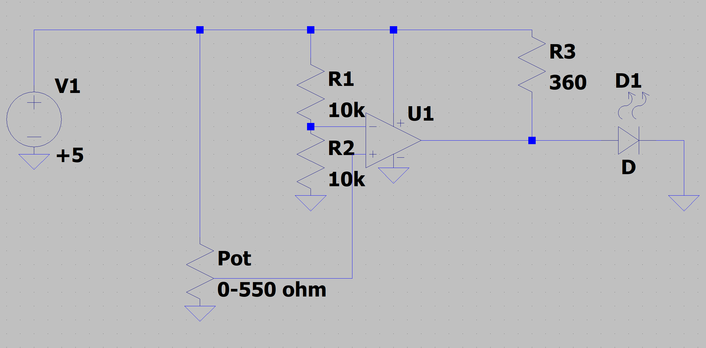
This is what I have so far as a test and it works. When the pot is adjusted to about 275 ohm the led comes ON. I can see that the pot emulates the LOAD but not 100% sure how to wire in my 12v load which as I said could draw 3-4A. Should I be protecting the non-inverting pin 3 ?
Hi Jim
What is U1.
If it is a LM393 you will probably destroy it in a short time because when it turns on you are trying to pass 33mA and it is rated 16mA with 20mA Max.
This is only a basic comparator circuit. I have already explained a circuit using a LM393 with the Hall effect device you were originally going to use but you choose to go down some obscure path so be it.
Just how you (or anyone else) are going to monitor current with that circuit is beyond my simple mind so I won’t try.
Cheers Bob
Bob,
Misunderstood you from before. Didn’t see using the LM393 and the Hall effect sensor. That now makes sense. Oh and been a long time since I have been down at this level. Obscure path was not connecting the sensor output to the comparator. Will redo it and please be assured that I am very grateful for you help.
Thanks, Jim
The resistor values should suit the device You discussed with James on the phone using the ACS723 IC.
Anything else may need a rethink and calc of R1/R2 ratio. The circuit values (9k1 and 10k) will work depending on where you want the switching point and the sensitivity (mV per A) of the particular unit you use.
The LM393 is a dual comparator so if you intend using 2 indicators it might be possible to just use the other half of the IC.
Got it working so many many thanks, very much appreciated. I had to play with R1 a bit with the older ACS712 chip but it works.
First image is my psi supplying 12v to one of my telescope control boxes with the 12v showing available but not on. No led lit, second image. Then I make the supply available and the led lights up as there is a small drain from the meter and leds on the control box, image 3. Switching more of the load on and the led increases brightness, image 4.
Hi Jim
Before you attack a circuit board.
Can you post a circuit of EXACTLY what you finished up with.
That should not happen. The LED should switch fully on not partially as you show.
There is one possibility. You may have fluked the exact position of switching causing the LED to toggle on and off at a rapid rate giving the appearance of being dimly lit. If you can post a circuit (schematic) and it is exactly the same as I provided (except for R1) this toggling can be avoided by introducing a bit of hysteresis with the addition of 1 resistor (Schmidt trigger).
From what I can see on the pic it looks OK but difficult to make out resistor colours and exact connections. If you can draw that circuit with EXACTLY what you have this will clarify resistor values.
Cheers Bob