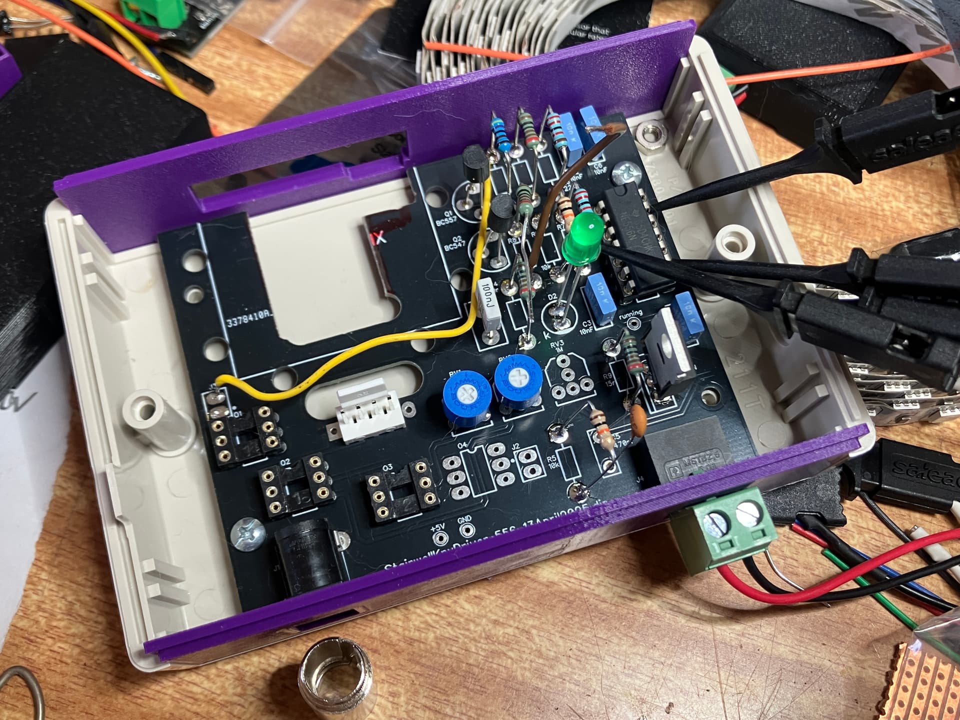
(I love these PacTec enclosures, which Mouser sells in multiple sizes in cream & black. The purple bits are 3D-printed front and rear panels, perfect for square holes.)
Does anyone know where I can hire/rent/borrow a CRO here in Newcastle for a couple of weeks?
If you happen to have a modern CRO/DSO not doing anything for a bit, I can pay in cash, or home-made chocolates if that’s your achilles heel.
While I cant help out with a CRO to rent, I was wondering what you want to see.
the Saleae can be very handy and it has both the digital and analogue levels.
Since its a 556 I assume its a digital clock your trying to debug.
If you could go over what you want to measure and a screen shot of the saleae we might be able to help a little.
What I’m euphemistically calling ‘a HR joint’ on one leg of C2 was giving me really whacky - but consistent - readings on the Saleae, and I wasn’t trusting it. It’s telling me what I’m expecting to see now with some solder on BOTH legs!
Let me reassemble and test it, but I’m feeling positive.
Thanks for responding and giving me the incentive to revisit it.
Sounds like a classic case of the circuit behaving as soon as it knows it’s being watched. Good to hear the Saleae was vindicated in the end, and thanks for the schematic and photos, always appreciated.
And Michael, for your supportive troubleshooting offer, I reckon Greig owes you at least a few handmade chocolates … or a signed photo of that glorious PacTec enclosure setup!
Looking forward to seeing the finished project once it’s off the bench.
Ryan, I’ll drop some chokkies to Core on my next visit and see if they’ll kindly distribute or enjoy them on @Michael99645 's behalf.
Looking forward to seeing the finished project once it’s off the bench.
It’ll take a while, but I’m prepared to oblige.
I’m as guilty as the next person of ‘prototyping’ a theoretical design into DIPTrace and wait for a $2 PCB to arrive before actively testing the theory.
I’m pleased to report this design looks to have been a success (once you remember to solder ALL the pins), but failed on the mechanical aspects - as evidenced by the hacksaw mods in the original image.
Next time I’m placing a JLCPCB order I’ll get them to do another version for me, which should then become the finished product. (This also goes some way to explain why most of the components are airborne, so they can be clipped to for testing and then easily removed to be re-purposed to the “v2” PCB.)
Robert I was being a good boy! I only soldered one leg, then went about other things, intending to return after the joint (component) had cooled to do the other leg.
Clearly there was a break in sessions and I thought I’d finished, or my eyes failed me - increasingly a problem unfortunately - and I jumped a little prematurely into testing.
Don’t think so. Usually solder both (or all) legs of a component at the same time unless I intend to insert another wire or something into the same hole. Very rare occurrence though.
Cheers Bob
It seems you’ve got it all sorted Greig which is good news of course - but just in case you’re bothered by anything similar in the future: If you’ve got a RaspberryPi handy, then you can install “PiScope” on that and it will emulate an oscilloscope (or logic analyser) and more than likely give you a very good description of what’s going on.