You haven’t specified what connection is on the power supply you intend using, but there are adapters available to add screw terminals to the supply. One of the most common is this one:
1 Like
Hi @Robin57159 - thank you for your reply! That is the jack I’m using. I just want to be sure it is ok to connect the 5V from the barrel jack directly to the 5V pin on the Pi.
Yes you can connect a 5v supply to the RPi gpio pins to power it. Here’s an article from the MagPi magazine about powering the RPi.
Now go to bed 
3 Likes
When i tried to run the code to test the LED’s i received the error: Could not resolve host: coreelec.io
That domain definitely still exists. Which part of your code is throwing the error? Have you got an internet connection?
Hi guys. I have this all working on a Raspberry Pi 3 Model B V1.2.
I am trying to use it to drive 4 WS2815 strips. When I put one strip on GPIO18 (PIN 12) and one on GPIO 13 (PIN 33) I can drive both strips and everything works fine. I’m trying to find another 2 GPIO pins I can use in this way. The only other two pins I can seem to use without causing a seg fault are GPIO 19 and 12. However, when I connect all 4 strips, I get odd behavior. What I tell the strip on GPIO 18 to do, the strip on GPIO 12 also does and what I tell the strip on GPIO 13 to do the strip on GPIO 19 also does. Any ideas how I can control 4 strips independently?
EDIT Upon further reading, it appears only the PWM module can control two strips independently but can control up to 2700 LED’s. My strips contain 480 each so I believe I can connect the end of one to the start of another to enable control of all four. This will make coding difficult since I’ll have to create a second set of functions that start at LED 481 for the secondary strips… Any other ideas are welcome
Thank you!
Hey Paul,
It sounds like you’ve found the best option, in this case, I’ve checked in on other solutions, and generally, the best way to be able to get away with it is to use a separate microcontroller as a driver for your LED and then communicate with that from your Pi, but in your project, that likely defeats the purpose of using the Pi for control in the first place. Make sure to let us know how you go with your project!
Bryce
Core Electronics | Support
Hi-
I’ve written a fair amount of Python for my Pis, though thus far I’ve only used “stock” libraries. I’ve not yet investigated this issue I’m running into which is shown below. I followed the instructions except instead of piping to bash directly I created and then ran the script from the command line. I didn’t notice any problems during the build/install. I’m expecting the import refers to python/rpi_ws281x.py, but Python isn’t finding it.
I skimmed the comments and this looks similar to what [Andrew125975] was seeing. “python -V” returns “Python 2.7.16” (although I note the she-bang line in the script uses python3. I believe specifying python on the command line will force the older Python.
Traceback (most recent call last):
  File "strandtest.py", line 9, in <module>
    from rpi_ws281x import *
ImportError: No module named rpi_ws281x
Before I dug further I thought I’d ask if this was familiar. The instructions and script seemed pretty straightforward.
Thanks-
Did anyone figure this out? Chris has the same problem:
1 Like
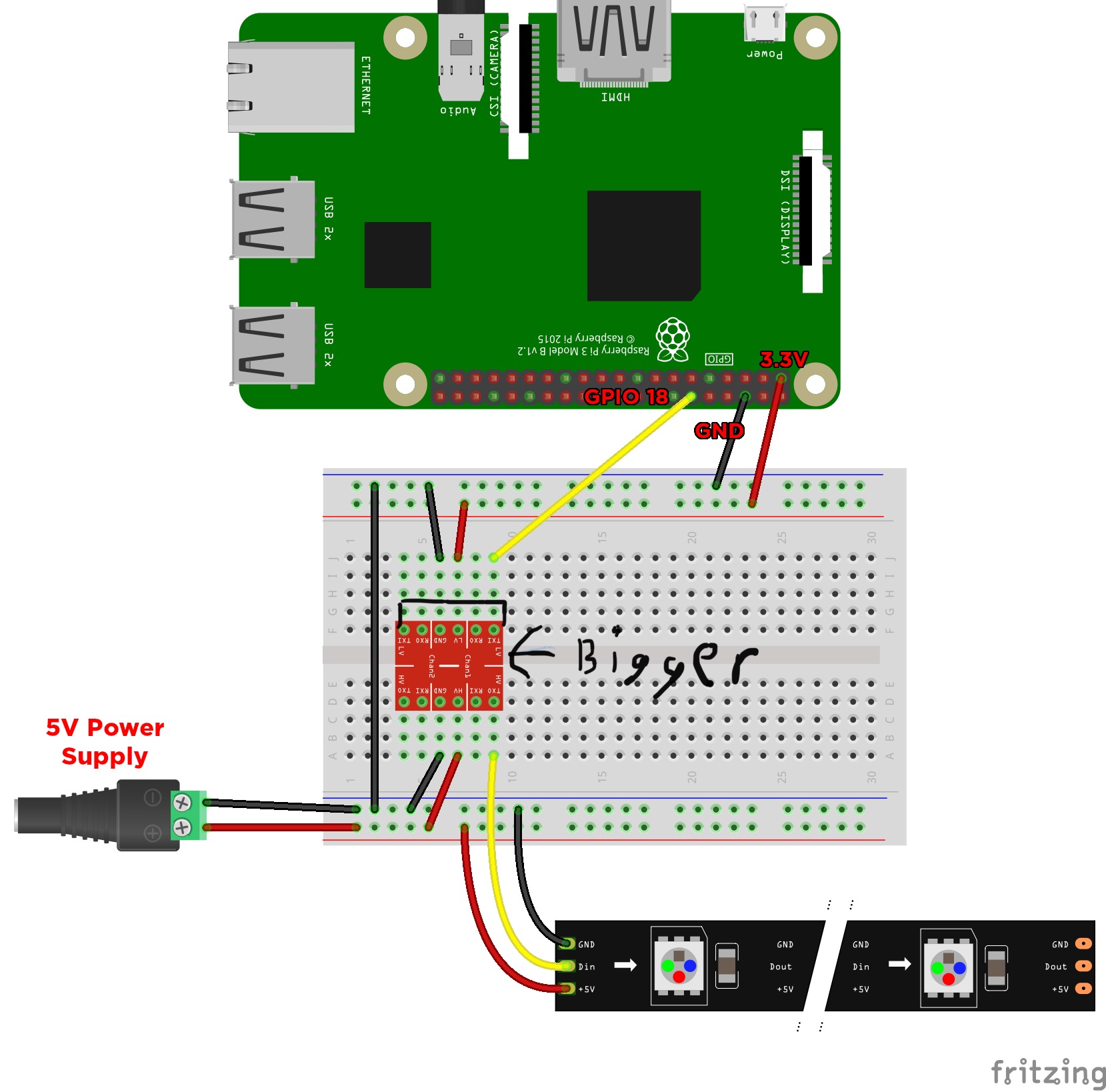
Can we just use the 5v GPIO on the pi? because in this diagram we use GPIO 3.3V and logic level converter to raise it up to 5v.
Hi Daryoush,
You can use the 5V and GND pins on the pi to “pass-through” the 5V power from your USB power supply, and provided your supply has enough current capacity to power both the Pi and the LEDs you could power a small strip this way, but I wouldn’t recommend it.
All the GPIO pins on the Pi are 3.3V only, so you would need a level shifter to control the LED strip, as the WS2812 modules only see logic above 0.7*[Whatever voltage you are powering the strip with], so 3.5V in this case is too high compared to 3.3V (the logic level of the Pi)
-James
1 Like
Thank you James
1 Like
why you take 3.3v and switching we can take it directly from external voltage just we give GPIO to RGB data
I guess it is only matter of time before another person has this issue, so all i did was ran the command below (from here) after following the instruction on this tutorial page. It is possible that the tutorial script has errors.
sudo pip3 install adafruit-circuitpython-neopixel
2 Likes
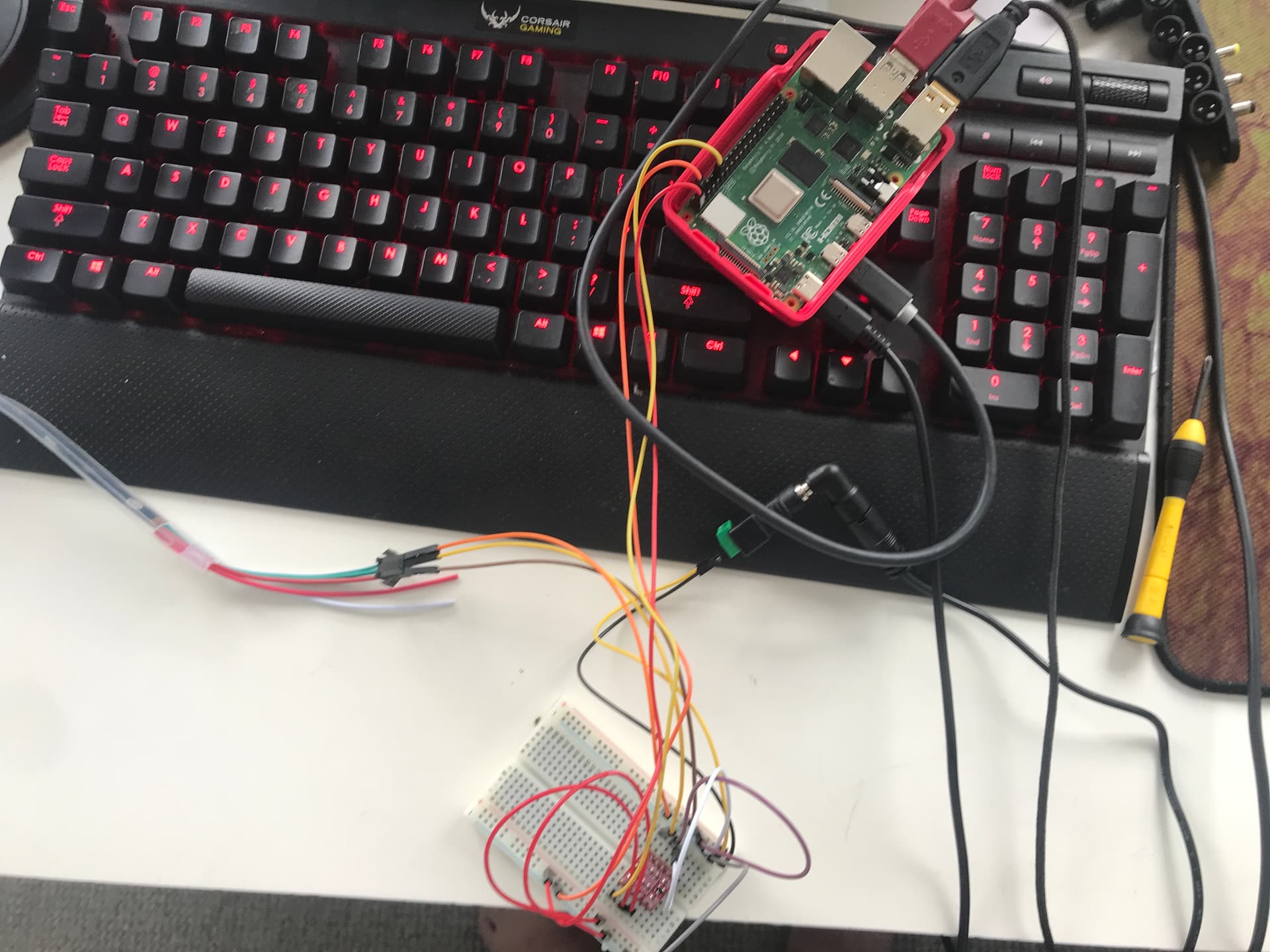
Hey I’m trying to set up my led and they don’t seem to be turning on I’ve done all the code and wired it all and I can’t get the led working I am new to all of this stuff and this is my first project does anyone know why?(my desk is a bit messy sorry) image|666x500


2 Likes
Hi Lewis, welcome to the forum!
How many LEDs are you trying to drive? They can get quite power-hungry, and some types of strip will not light at all if they aren’t getting the current they’re after.
If you could also make up a small schematic of how you’ve got everything connected, that’d be most helpful (hookup wires like these can be a little hard to follow, especially with a LLC we don’t have experience with. Sometimes even just drawing up the schematic of how things are supposed to be connected points out
Keen to get you back on track!
-James
3 Likes
Everything is the same except that I have a different logic level converter as I don’t have the equipment to solder something I think thats the problem I have a different logic level converter the link is the one I have also sorry for the bad diagram
Also my lights are 5m by 30 so 150 neopixels which I think should be enough as I do have a different power source
Also sorry I could not respond so quickly as I blew my rasberry pi put 9v through it oops it’s ok as I got another one
Thanks for the help James
-Lewis
image|506x500
1 Like
Thanks for the code, video and the discussions everyone.
Was able to install and run the program successfully.
I have a question: Is there a way to stop the white LED flashing every half a second or so, while running the script? I have zero python experience. Will appreciate any help.
G
Edit: Solved the white LED blink issue.
I had the LED strip connected through GPIO 10 (SPI). Using a RPi4, the minimum core frequency has to be set to 500 as per here.
On a RPi 4 its dynamic frequency clocking has to be disabled, since it will desync the SPI clock. Do this by adding this line to /boot/config.txt. (core_freq does not have to be changed, since the default value of 500MHz is SPI compatible)
core_freq_min=500
Just added the parameter under the overclock commented line as follows
#uncomment to overclock the arm. 700 MHz is the default.
#arm_freq=800
#For WS281x SPI use
core_freq_min=500
Hope it is useful for someone.
2 Likes
Pardon my ignorance, Lewis, why are you connecting the LV + and - to RPi? you need to connect only the ground. I am using a level shifting chip instead of the Arduino thingy ((check the first Fritzing schematic in this webpage)
Instead of using GPIO 18, I am using GPIO 10 (Have to enable SPI in Raspberry Pi preferences under the interfaces tab) (Thanks to TimH’s post in this thread above). Also need to comment out the Line 14 in the strandtest.py and remove the comment (#) from line 15 (Pasting below how I have it - highlighted in BOLD:)
LED strip configuration:
LED_COUNT = 300 # Number of LED pixels.
#LED_PIN = 18 # GPIO pin connected to the pixels (18 uses PWM!).
LED_PIN = 10 # GPIO pin connected to the pixels (10 uses SPI /dev/spidev0.0).
LED_FREQ_HZ = 800000 # LED signal frequency in hertz (usually 800khz)
LED_DMA = 10 # DMA channel to use for generating signal (try 10)
LED_BRIGHTNESS = 50 # Set to 0 for darkest and 255 for brightest
LED_INVERT = False # True to invert the signal (when using NPN transistor level shift)
LED_CHANNEL = 0 # set to ‘1’ for GPIOs 13, 19, 41, 45 or 53
Also, make sure you are connecting the data where the DIN arrow goes inward on the strip. The LED strip I have as connectors on both ends. Only the female connector is on the end where the arrow points inwards to the LED strip. That is if you have more than one connector. From the way I see your connection of the jack (next to your keyboard, it looks like the jack has male connectors. Just double check if the DIN arrow is in the inward direction.
Hope this helps.
3 Likes
Just setting up a PiZero WH for running the lights. Found out that the core_freq_min=500 modification applies to Pi Zero W as well. It was also giving that white LED flash, interrupting the strandtest.py sequence. I will be going to bed less stupid tonight. 
6 Likes