Hi, I am currently trying to build an ADC, and I am having a few issues with the circuit as a whole. I will upload the circuit diagram, as well as note the parts used.
The resistor array at the top of the diagram is to divide the voltage so I have a range of 0.5 - 1V for my comparators (LM324). It is then put through a pull up resistor because it has an open comparator output and then put into the EXOR gates (LM4070) which should give me a binary output. I will try and give as much detail as possible since I have a feeling this is may be a small issue.
This is the diagram I have based my circuit off
NOTE: this is for 2 bits, I have expanded mine to 24 bits
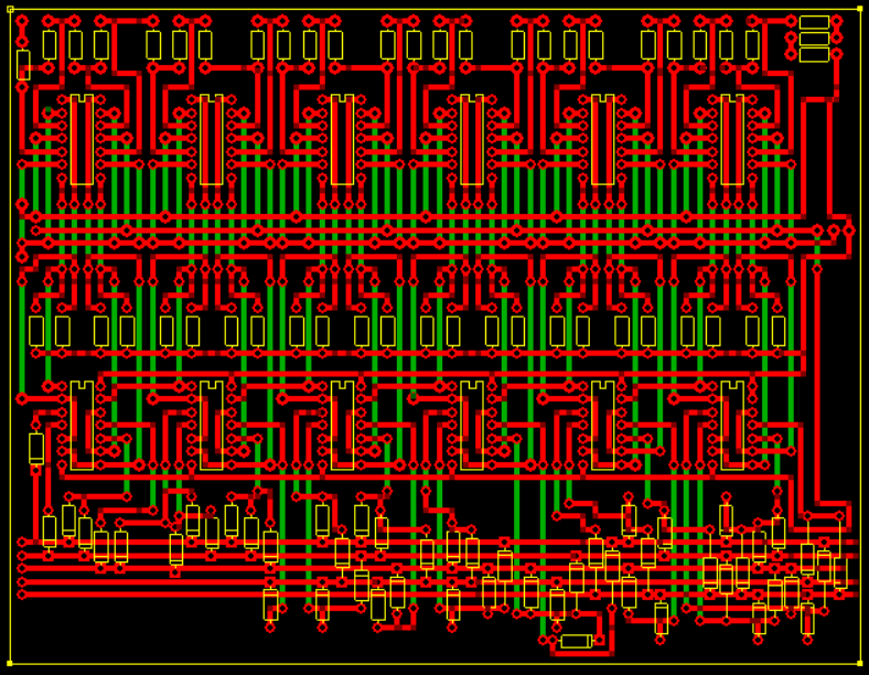
This is my circuit (I designed it myself, so there will definitely be issues)
The green lines are connecting wires. The top of the circuit has the comparators and the bottom has the EXOR gates. For all of the IC’s they are supposed to have the 14th pin in the top right of each socket. The three random pads in the right-middle area of the board is for the sensor, the left pad is ground, middle is analogue input (between 0.5 and 1V) and the right pad is high (5V).
One of the issues I have come across is the binary outputs are not expected. Also I think the comparators may be working with values too close together because I’m getting some really strange outputs.
Also, this is a little irrelevant, but it is connected to a TMP36 temperature sensor however currently connected to a pot for testing.
The LM324 is NOT open collector output so a pull up resistor on the output may be confusing the issue.
That tutorial linked refers to LM339, this IS open collector output and DOES require a pull up resistor.
The LM339 is a dedicated comparator and may be a better choice. You may need a little bit of hysteresis to prevent “chatter” or instability at the switching point.
Also bear in mind the circuits shown are probably simplified for descriptive purposes and the real thing (like dedicated ADC ICs) may have a degree of hystereses built in.You are obviously creating an ADC with discrete components. A worthwhile venture for educational purposes.
Cheers Bob
EDIT:
The application notes shown at the end of the LM324 when used as a comparator DO NOT show a pull up resistor.
Hi Andrew
I am a bit puzzled by the circuit showing comparators, gates and diodes. This circuit seems to be an extract from that tutorial link.
In that tutorial the text refers to Exclusive “OR” gates yet the circuit clearly shows exclusive “NOR” gates. I have been trying to figure out how that 2 bit circuit could work and the only conclusion that I can come up with is that the 2 lower gates should be XOR gates and the upper one should be XNOR or XOR with an inverter.
This might account for your funny results. I may be wrong but have a close look at this and see what you come up with.
Cheers Bob
Hey Bob, thank you so much for your help, I have been working on it in the past few days and ironed out some basic shorts and removed the pullup resistors from the circuit by cutting a track. I was testing it and it works! Somewhat. I will be working on it in about a week, but I really think your suggestions worked. thank you so much, I really appreciate the time you have taken to look at it. Thanks
Hi Andrew
I can’t understand how you came to make a circuit board without getting the whole thing to work first.
I would get the basic 2 bit part working first before becoming too ambitious.
Also have a look at those gates. I don’t quite get how the author of that tutorial talks about XOR gates in the text and draws XNOR gates in the circuit. I haven’t drawn out a truth table for the whole 2 bit circuit but I think I am right in what I say above. I am not a “digital” person really but I think I know enough about gates etc to work out what is happening in that little circuit.
Cheers Bob
That’s fair enough, I haven’t really been super descriptive. If you’d like I can send you the IRL photos? But I knew this would work because a mate of mine made one with similar components except for the LM339. So I knew it should work, I also verified with him and a teacher a number of times
Hi Andrew
Could be enough difference between “similar” and “the same” to prevent yours working.
The LM339 is NOT an OP Amp and an OP Amp is NOT an LM339.One of the mail differences is the open collector output of the LM339 and the fact the output will swing almost rail to rail.
Cheers Bob
This comment is purely academic for your project so don’t take offence.
You have expanded to a bit less than 5 bits. for the full 5 bits you would need 31 comparators, you have 24.
For 24 bits you would need by my calculator and the formulas in that tutorial 16,772,215 comparators. (2^24-1) plus all the other bits.
Just change your above statement to 24 comparators or steps.
Cheers Bob
Hi Andrew.
Let us go back to the tutorial you linked.
The author has me (and others) totally confused. If you read the text description and I quote
“When VIN is between 0 and 1 volt, (<1V) the input on all three comparators will be less than the reference voltage, so their outputs will be LOW and the encoder will output a binary zero (00) condition on pins Q0 and Q1. When VIN increases and exceeds 1 volt but is less than 2 volts, (1V<VIN<2V) comparator U1 which has a reference voltage input set at 1 volt, will detect this voltage difference and produce a HIGH output. The priority encoder which is used as the 4-to-2 bit encoding detects the change of input at D1 and produces a binary output of “1” (01).” unquote.
This scenario used with XOR gates will work and give the required binary value.
The problem lies with the circuit. The inverting inputs (-) of the OP amp have to be connected to the reference points and the non inverting inputs (+) connect to the variable. This error has been picked up by others in the comments at the end of the tutorial.
The second problem is that although he speaks of using XOR gates he has drawn XNOR gates.
The circuit as drawn would produce a “1” or HIGH at the outputs at all times I think.
I believe that reading your original post that you are using LM4070 which I think could be CD4070.
I think this would work and produce the correct binary output if you reverse the OP amp inputs. Connect the reversing input to reference points and connect the non inverting inputs to the variable. Continue to use the 4070. (the XNOR version of this IC is 4077).
This is going to involved some careful track cutting and linking but is the only way this will work.
Cheers Bob
Is your input voltage stable? If not, you’ll need a filter to take out any signals above your Nyquist frequency. Otherwise, you will get very strange results.
From this end of the conversation you have to assume some things A stable power supply is one of those things as without this nothing much is going to behave as expected.
If Andrew wires this project according to the circuits drawn he is going to get some strange results anyway. I had a quick look at the artwork he posted and I think he has indeed wired as per circuit from what I can make out. The reversal of the comparator inputs has been picked up in a couple of comments at the end of that article but nothing has been done to correct the error. The text and truth tables are correct but the circuits don’t match.
Cheers Bob
Hi Andrew.
Before you go too far down the alteration path. It has been pointed out in a later thread on a similar subject to-day that that this logic will work with those comparators as drawn if you connect the last one to +V instead of ground. This is correct and I apologise as I had not considered “negative” style logic and only considered the positive aspect.
Cheers Bob