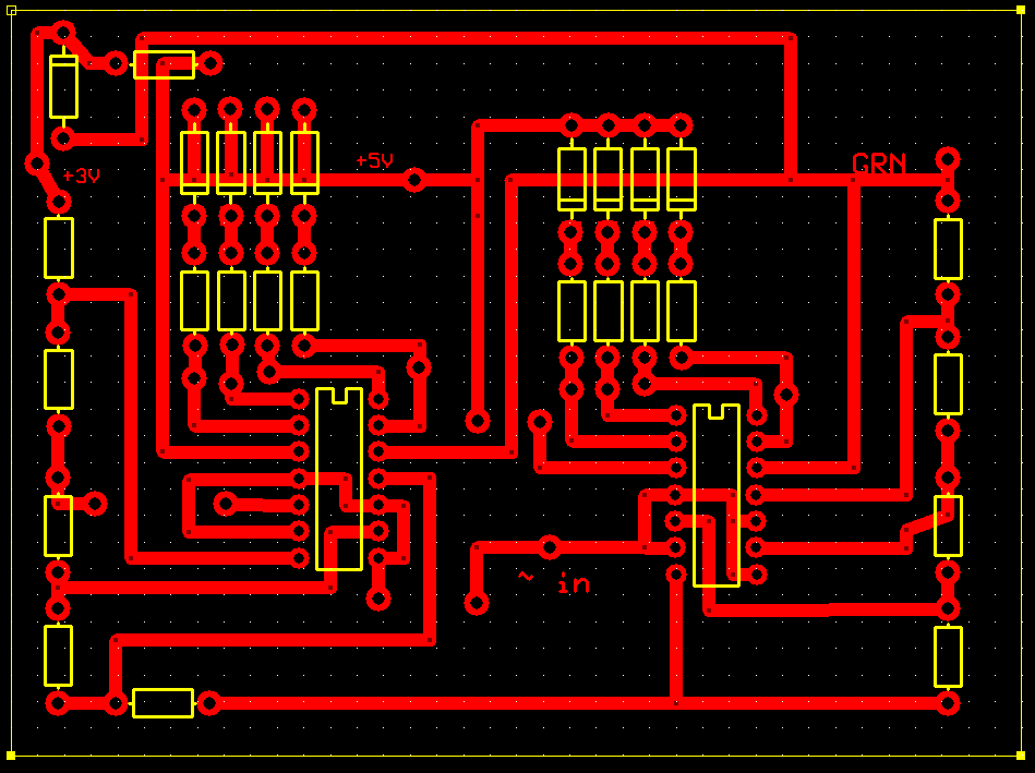
I have built an ADC based on the above diagram however scaled to 8,12 & 24 comparators, please note that the diagram includes two mistakes which were corrected in the construction of the actual circuit:
Pictured are XNOR gates, they should be ordinary XOR Gates.
The top most pin of the topmost XOR gate is tied to ground, it should be tied to high.
Mysteriously when the XOR gate (4070) outputs a logic 0 it is actually outputting approximately 1V. Ordinarily this would not be a problem however the multiplexer I am using (74LS151) to encode the signal is reading this voltage as a ‘1’ and causing mayhem.
The strangest part is that probing with an oscilloscope on the input of the diodes (1N4004) / output of the XOR gates every single diode is either obviously on (+5V) or obviously off (0V) and somehow this small voltage is mysteriously appearing.
For reference I tested the multiplexer on its own by manually shorting the inputs to ground and found it to be working perfectly.
Before anyone comments that it is likely a soldering mistake or other similarly silly error I have two independent PCB’s exhibiting the same behavior.
I expect to solve I either need to remove this mysterious voltage or somehow change the threshold where the multiplexer reads a voltage as either a 0 or 1 to be slightly higher.
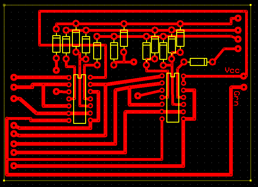
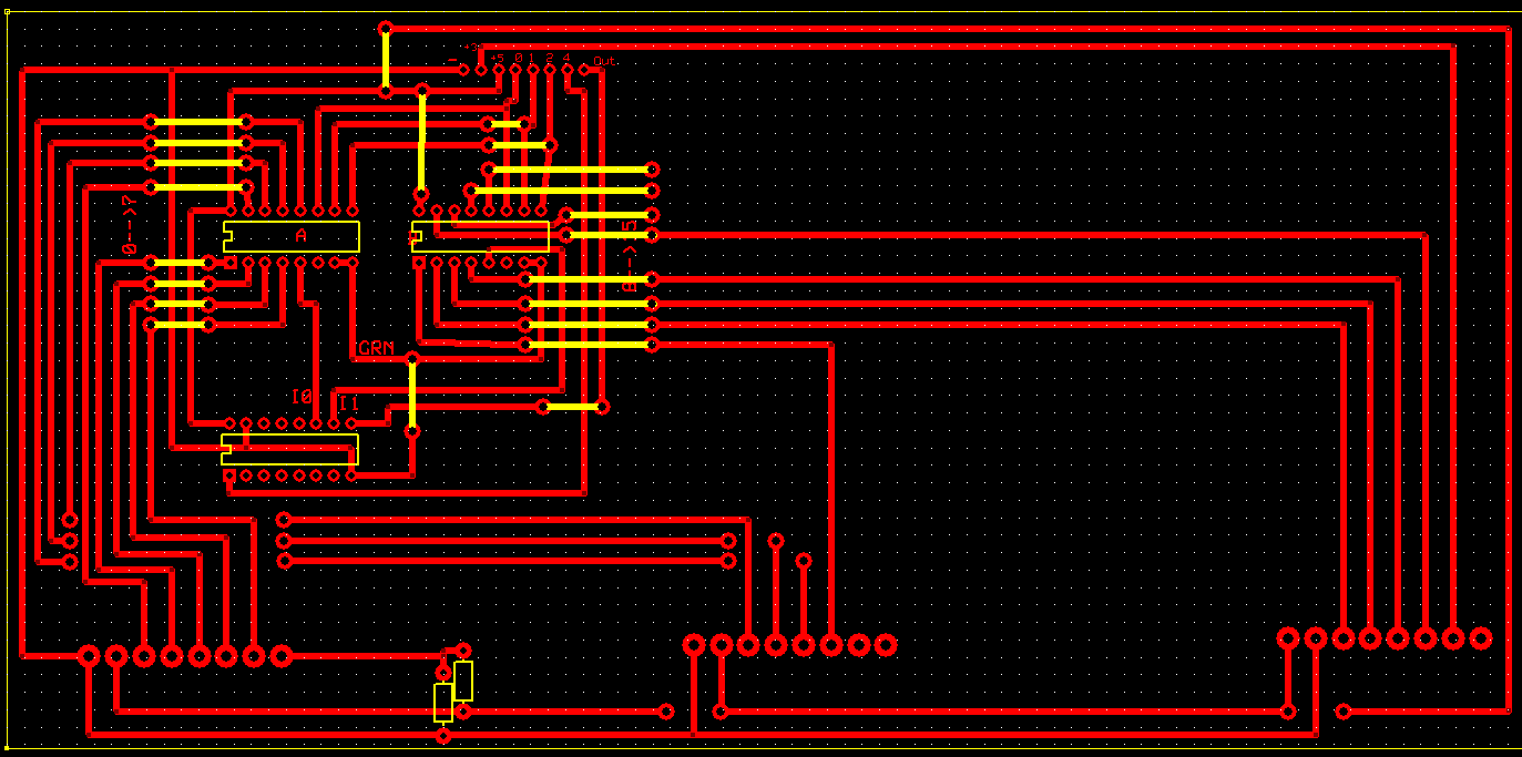
Although I doubt it will be helpful but below are the three relevant PCB schematics:
The ADC and ADC encoder are connected externally by wires their respective inputs and outputs being below the pull up resistor on the ADC and on the left side of the ADC encoder.
This schematic will take three ADC’s as inputs to plugs on the bottom of the diagram, the ADC above is connected to the rightmost set of inputs. The other ADC’s have been omitted as they are near identical to the one shown.
Thanks in advance for any help you are able to offer, Jem.
Hi @Jeremiah177112 - cool project
If I’m interpreting correctly, you’re observing:
1V at the output of an XOR gate (measured with multimeter)
Stable voltage (eg. 0V) at the output of an XOR gate (measured with a scope)
What happens when you measure the voltage with both devices simultaneously?
Where I’m going with this is that the input impedance of the equipment are different. The scope on 1x setting will be about 1MOhm, while the multimeter will be 10-20MOhm. The input capacitances will be quite different too.
It could be that the way the circuit is being measured is causing it to oscillate.
Hi Jeremiah
Andrew had a similar problem when building this ADC from that tutorial.
The gates should be XOR but they are shown as XNOR as you have pointed out.
The other error which had been picked up in the comments at the end of that tutorial is the comparator inputs have to be reversed. That is the reference should be connected to the inverting input and the variable connected to the non inverting input.
The top XOR gate should have on input tied to ground.
If you draw up a truth table you will find this error has to be corrected before the ADC will work.
I notice on your PCB drawings you have pull up resistors on LM339 outputs, that is correct these are required but what are the series diodes for? I think the only thing they would do is drop the “HIGH” voltage by 0.6V.
I can’t explain this. Exactly where are you measuring this phantom voltage, at the XOR outputs or the diode outputs. I note the author of that tutorial seems to think pull down resistors are needed on the bit lines (diode outputs). I would not have thought so but he must have had a reason. I note you have not included them.
I am not trying to be funny but it would not be impossible for there to be a mistake on the artwork so the same problem would be on both boards.
Cheers Bob
Thanks for your quick replies, to clarify a general point the 1V was actually an estimate based on the oscilloscope without precise markings as to the voltage, in actuality it is 0.4V.
To clarify it is an old analog oscilloscope and its difficult to precisely read quantitative measurements despite being a relatively precise machine.
I have now measured the same phenomenon with a scope and with a multimeter in each case to the same results.
Nothing special at all both voltages are identical to that which is measured individually.
I have read the forum thread from Andrew with a similar circuit, I acknowledge that the cause of the mistake is the comparator polarity but if the polarity is reversed and the top XOR gate pulled high the circuit continues to operate as normal due to the symmetrical nature of the XOR gate truth table. I.e. in the state of input is 0V the comparators all output 1 which turns off all XOR gates, in the next state up the bottom XOR gate is activated as its top contact is high and its bottom low. That being the comparator polarity can be wrong if the logic circuitry is handled differently.
The output of the diodes report a phantom voltage, the inputs (apparently being the only possible source) do not report such a phantom voltage.
I am also unsure of its existence, up until the inclusion of the multiplexer this slight phantom voltage was a non-issue, i.e. my raspberry pi was happy to read it as a ‘0’. You make an excellent point as including one would theoretically pull the phantom voltage down to ground but still allow the ‘1’ to exist.
Perhaps I wasn’t clear, that statement was attempting to refer to a mistake made after the creation of the artwork, e.g. a poor solder joint, an accidental disconnection of a PCB trace ect.
That decision was naïve of me and I realized my mistake quite late into building the board and since it didn’t appear to hinder circuit operation I didn’t feel the need to remove it, i.e. “if it ain’t broke don’t fix it”
You are quite correct. I had not thought of “negative” type logic, I just went down the “positive” trail.
Is this “phantom” voltage present with the multiplexer disconnected. Maybe it is the MUX that needs the pull down resistors. I am not familiar with that device co can’t comment. The XOR can only source 0.5mA to 1mA so 10kΩ would be a minimum value I would think. You might also check that the MUX does not have high value pull up resistors built in although I would think this unlikely but you never know.
Cheers Bob
I had considered this and unfortunately produces no change to the output.
I’ll try it on a breadboard beforehand with only one XOR gate but I’ll start with 10K and adjust accordingly.
To ensure that I have understood the intention perfectly in this situation a pull down resistor will pull such a small phantom voltage to ground and so will behave better with the mux but a high will not be effected enough to cause the MUX to mistakenly read a ‘1’ as a ‘0’.
I fear this may be likely as leaving a MUX input as open circuit causes it to output a 1 when selected. This unfortunately doesn’t explain the phantom voltage since it still occurs when disconnected. I acknowledge that I am somewhat out of my depth beyond this point and don’t understand why a pull up resistor is causing the 0.4V to be read as ‘1’ but my intuition indicates that, at least theoretically, pull down resistors in wired as the original diagram and Bob recommended would fix the problem.
Hi Jem
Well that is a mystery. If it is 0V at the diode input (XOR output) and still present at the output with no MUX connected you really do have a gremlin. I am assuming all the diodes have the same problem. Can you lift the cathode end of the diodes one at a time and see what happens. Also measure at the cathode end while they are lifted might provide a clue.
Thinking about this further, pull down resistors WILL be required, because of the diodes the XOR gate will not be able to pull down the MUX input (blocked by the diodes).
Cheers Bob
All diode inputs are obviously 0 or 1, for all diodes on both boards I tested and yet both still show this phantom voltage.
That is a good idea, thanks.
I intend to wire up a single xor gate on a breadboard and see if I can replicate the phenomenon, if I can this can also provide absolute certainty as to the necessity of pull down resistors and allow me to confirm the value required.
Its somewhat strange then that when I tested earlier by connecting the outputs of the diodes directly to my Raspberry pi I found it was working correctly. But regardless thanks for the tip.
Hi Jem
An experiment worth looking at. The data sheet for the MUX seems to indicate a common base input . That is the input is to the emitter of a transistor. Try removing any pull down resistors, reverse the diode polarity and let the XOR pull the MUX inputs to ground.
Just another thought. It has been forever since I have had anything to do with common base configuration, not very common.
Cheers Bob
I’ll be sure to try all the changes you’ve recommended and see if I can get any helpful results. I’ll be sure to update the forum once I get a chance to test everything.
Thanks again for all your help Bob, absolutely incredible.
Hi Jem
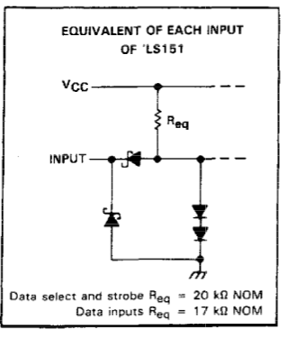
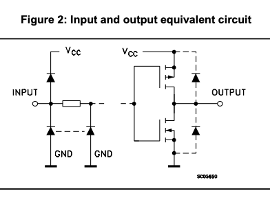
Closer look at the MUX data sheet.
This could be where your phantom voltage is coming from
You would have VCC coming via a 17k (or 20K) resistor and forward biased diode to the input. Held down (???) by a Zener diode of unknown characteristics to the input point. Almost like a disguised pull up resistor. In this case a pull down resistor would not do much.
This leads me to believe the good option would be to turn the diodes around and let the XOR pull the inputs down. This will leave 0.6V (diode drop) at the MUX input which should be seen as logic low. If in doubt or you think this would be too high use Schottky diodes which have a lower forward voltage drop.
Cheers Bob
EDIT. The point at the bottom of resistor Req would be at about 1.2V, which would be the voltage drop across the 2 series diodes to ground. Measured at the “input” would be a bit below this due to the drop across the input series diode. Suspicious what ???
I think the problem here is that if the input to the diodes is an 0, then the diode output is floating. So the phantom voltage could come from anywhere. The pull down resistors are necessary to remove the problem. However, attempting to drive TTL devices with CMOS devices is not a good idea. TTL requires current, CMOS is designed for high impedance voltage. This complicates the calculation of the pull down resistor values. Changing the 74LS151 for a 74HC151 should work, using high value pull down resistors, say 47kΩ ohm. The input impedance of the HC series is typically >1MΩ.
Can’t agree with that. Voltages come from somewhere and have a reason. I think the reason I outlined using that equivalent input circuit is valid.
Pull down or up resistors are to prevent an input floating in limbo land. If internal pull ups are used an external pull down will do nothing except modify the inactive voltage point a bit. In the above case I think “Req” is a pull up and the actual voltage is clamped by the 2 series diodes to Gnd. Therefor the input defaults HIGH and has to be pulled to ground to do something.
The rest regarding TTL and CMOS I agree with. I had a quick look at a couple of Data sheets for the HC variety and the only equivalent input circuit I came across was this
which does not say much except that the input voltage swing maximum is clamped to the supply rails (VCC and GND) and the output is switched rail to rail. No indication of an internal pull up so an external pull down resistor would probably be a good idea. Measuring the voltage without and with a pull down should indicate if an internal pull up is present.
Cheers Bob
I got the impression the voltage was seen with the multiplexer disconnected.
Maybe I misunderstood. It is irrelevant anyway, pull down resistors are required because of the diode logic and should disappear the problem.
HC logic doesn’t have a pull up or down resistor. The input is clamped for ESD protection. Within the working voltage 0 to Vcc there’s hardly any leakage. This has some useful information.
Hi Alan.
Pretty good info on that link. Particularly the interface info from the last paragraph on page 18 onwards to end page 24.
The difference with Jem’s problem is there is a diode in the path.
I may be wrong but I still think the comparator and priority circuitry has to pull the MUX input LOW to make anything happen and HIGH is default. I haven’t got enough bits on hand to do any experimenting so will have to leave that to Jem.
Cheers Bob
For anyone still curious or reading this in the future I have discovered, after much trial and error, and many headaches, that the pull down resistors implemented as Bob suggested were effective once an appropriate value was found, I was lucky to accidental stumble on the fact that ~3.9K worked wonderfully for my own circuit. Thanks again for everyone’s replies.