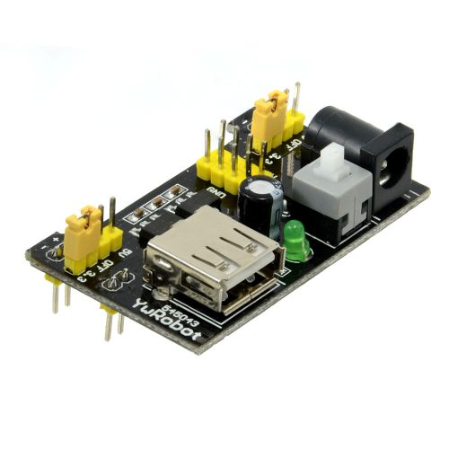
Get your prototype online faster with a premade power supply module that can be powered by a DC Adaptor. Switchable 3.3V/5V rails and 5V USB output to cater for almost all common digital designs
Normally in the device being powered. The power source has no way of telling which way around the powered device is connected except for possible overcurrent when something fails.
Cheers Bob
According to the only schematic I can find, which might not apply to this specific item, the only reverse polarity protection would be provided by the regulator. So whether or not there is protection would depend on which regulator is used (although typically it is not quoted as being provided).
However one supplier that appears to be stocking the same item mentions a reverse protection diode on the input, and it appears from the image as though there is something that could be a large diode (M7?) adjacent to the power socket. Diode protection would create a voltage drop which would affect the minimum dropout voltage of the device, which would be inconsistent with the quoted minimum supply voltage of 6.5 V. In the absence of confirmation I would be careful in selecting the correct plugpack.
Purchased one of these sometime ago, managed to kill the 5V regulator, replaced with a large style one, not pretty but works.
The middle pin of the DC socket is connected to the Diode.
The other side of the diode goes to the 5V regulator input.
The output of the 5V regulator goes to the input of the 3V3 regulator.
It is useful for basic testing of 5V and 3V3 circuits but does not provide enough protection in my opinion.
It has a number of limitations.
Too easy to change the voltage and damage whatever circuit is being tested. I am forever making sure the jumpers are the correct way around.
The pins would not fit the breadboard I wanted to use, one side was removed and wires soldered on.
I think the 5V regulator failed because it must cater to the DC to DC input drop (12 - 5 = 7V) and also supply the 3V3 current.
You have got to watch this with linear regulators such as the LM7805 and the like. If you want to draw larger currents like 1A or so the best operation is with the input voltage no more than about 3V above the output. In your quoted case at 1A the regulator would have to dissipate or get rid of 7W which a 7805 might handle with its TO220 package but even then I would be thinking about a heat sink. Some of the physically smaller devices would struggle I think. The usual method of getting larger currents is to use one (or several in parallel) pass power transistors with the lower power unit providing the base current. The output here will be lower than the control regulator voltage by a value equal to the base/emitter voltage of the transistor(s).
Cheers Bob
The USB A is primarily meant to be an output from what I can tell.
I can’t confirm without a schematic but I’m guessing the 3.3V regulator is powered off the 5V regulator so feeding in 5V to the 5V rail will allow you to get 3.3V.
These do exist. I have one at home for an old HDD enclosure. It isn’t up to the USB Specifications as far as I’m aware as USB A is only meant to be used for the Host and USB B is only meant to be used for a device/client.
The USB socket is to provide 5V output it is NOT an input.
The 5V comes from the Linear regulator on the board.
Confirmed.
Voltage path is 2.1mm socket to 5V linear regulator to 3.3V linear regulator.
This would place 5V on the 5V regulator output with nothing on the input, a condition linear regulators usually do not like. Modern regulators may be designed to work with this situation. Personally I would avoid it as a rule of thumb.
This board has worked well for me when I need both 5V & 3.3V for a small test circuit on a breadboard. The 700mA max current is an overestimation in my opinion.
I like the look of this board - that you can put 3V3 and 5V down whichever power rails you choose; and that it (claims to) provide a higher current (because you don’t know what future projects might want).
However i am concerned about the spacing of the header pins to the power rails.
The DFR0140 DFRobot’s Breadboard Power Supply takes 3 rows at the top of the breadboard, and since the power rails on my breadboards start at the 3rd row of tie points, the first 5 rows of tie points are unavailable.
The photos for this board, however, look as though the power rail header pins are at least 4 rows apart - and possibly not a multiple of 0.1".
Would it be possible to add a photo of this board mounted on a breadboard ?
If they fit a breadboard they will certainly be 0.1"
The two 4 pin header strips between the power pins don’t seem to be on the same 0.1" grid but as they don’t plug in to the breadboard this does not really matter.
The practice of having this sort of thing on a different grid to everything else is happening more often lately. This for some reason applies to mounting holes where provided. I am at a bit of a loss to understand why. I think some people like having nightmares dreaming up some of these schemes.
Cheers Bob
I have found it useful for these power adapters to design and print a small tab that slots into the centre groove of the breadboard and extends a little beyond the end. It provides support for the overlapping portion of the power adapter, and makes it a little more solid.
@Robert93820 and @Jeff105671 are spot on here, I’ll make a note to have a photo added with the product in a breadboard to save anyone else down the line.