This is a placeholder topic for “9g Micro Servo - FS90 (180 degree, 1.5kg/cm)” comments.

Easily add motion to your projects with the FS90, the staple Maker servo.
Read moreThis is a placeholder topic for “9g Micro Servo - FS90 (180 degree, 1.5kg/cm)” comments.
Easily add motion to your projects with the FS90, the staple Maker servo.
Read moreI’ve been keen to find an excuse to learn how to work with motors.
I think I’ve finally come up with a simple project that’s still inspiring enough that I’ll actually finish it.
I want two mirrors motorized mirrors to redirect a “laser” around a corner.
Some kind of low power (class 1) laser or LED spotlight.
I’m thinking one Mirror will have panning control and the other tilting control.
The challenges I think I will face are.
I’m happy to 3d print some flat surfaces and put some reflective tape on them to keep the weight down. Obviously real mirrors would be preferable.
I’m also after as smooth of a rotation so I can direct the laser.
I also need moderate speeds. Something like 5-10 rotations per second.
I don’t need full 360 rotation, somewhere between 45 degrees and 180 degrees will be plenty.
In-fact, I like the idea of the motor being restricted to certain angles for safety.
Even though I want to work with safe red lasers I still don’t want the risk of a bug in my code throwing lasers randomly around the room.
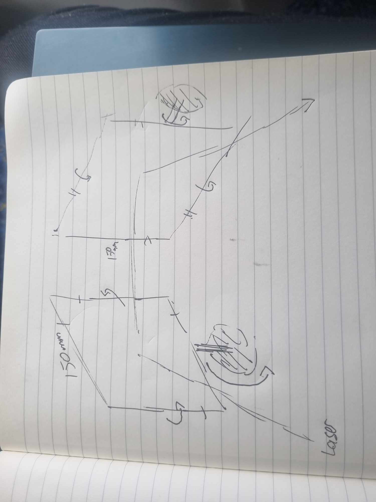
here is a quick sketch.
I’m currently imaging these support beams coming out of the back of the mirror that will be attached to either the servo horn or even just the servo gear itself. I’m open to superior suggestions.
Have I found the right motor for the job?
Have I bit off more than I can chew?
Thanks in advance ![]()
Pix. ![]()
Really cool project idea.
The laser scanners I’ve used in the past are usually based on stepper motors on the low end or galvanometers on the high end.
If you aren’t looking for speed to be able to create patterns with persistence of vision then servos should do the trick just fine.
I think glueing a rod or even just the mirror itself to the servo gear or making a 3D printer holder would work well. On professional inits I’ve torn apart the reflective surface is usually as close to the center of rotation as possible.
I hope this gives you some ideas for this project.
I think this drawing communicating that the diameter of the gear is 4.86mm?
If I just made a long plastic stick and drilled a 4.86 diameter hole in it… do you think It would press fit?
Alternatively I could drill some holes in the horns and use metal screws to attach something?
Hi Pix
I think you could find a splined horn which is circular with holes drilled and tapped already. The possibly come with the servo. Most servos I have (not many) came with a selection of horns.
Cheers Bob
Thats how I read it as well. Relative to the rest of the drawing dimensions, 4.86mm sounds about right.
I can see that a common choice for these motors are micro controllers like a Pico.
If I wanted to control it with a raspberry Pi zero 2 do I need any external hardware?
Should only need a solid 5V power supply and some wiring to get it going.
We have this guide here with some example code that should help you get started.
Hi Pix,
We also have this product with a guide, it uses a dedicated PWM IC so the Pi can handle all of its usual SBC tasks: Pimoroni Picade Pan-Tilt Hat (Full Kit) | Core Electronics Australia
Liam
Love that suggestion @Liam, might go for it.
I want to keep digging into the FS90 idea first because a big part of my goal for this project is to learn how to use simple motors.
Can someone help me with understand forces and motors?
Hard to explain via text so I recorded myself with props here.

Hi @Pixmusix,
I think the forces you want to know more about are Rotational Inertia and Angular Acceleration. They relate to torque but have a bit more to do with mass distributed across an axis of rotation rather than a point load. It’s been a while since I’ve done these sorts of physics calculations but there’s a lot of information out there on these subjects.
In terms of the forces that can be applied to the output shaft perpendicular to the axis of rotation, like the amount of weight you can put on an output shaft, is not a spec I’ve come across for servos before.
There would be a physical limit due to the limitations of the material but I don’t have an answer for that one.
Hi pix, Aaron
I don’t see that little plastic bit putting up with any sort of force in that direction, ie; right angles to the servo shaft direction.
I think this shaft with a mirror attached should be considered as an axle to be rotated. I think that is the intention. In this case I think it would have to be supported at both ends or at least the end furthest from the servo.
The other way would be to try it suspended in space and if it breaks or fails start again.
Cheers Bob
And you can get our latest projects and tips straight away by following us on:
![]()
![]()
![]()
![]()