The answer was in fact simple, just VERY HIDDEN or with-held. A shed load of digging for very little return. Yes this is VERY toned down from what I started to write less than 30 minutes ago …
So basically a SHT-30…
Nothing special at all. Simply the need to get to acquire the information gathered by a sensor, and return it for use by the Pi. … well a lot of sensors…
like
SHT-30
two rain buckets
two temperature & Humidity sensors Dfrobot SEN0277
light sensor TSL2591
a few roller levers ( yes simple on / off switches )
& many stepper motor(S) activate individually
There MUST be an easy way to do this on ONE Raspberry Pi 4.
on advice I purchased MCP3008 & MOSFET. All Useless as they are unable to be used to return meaningful results ! Thus far.
SO I have a lot of junk that is unable to be used due to the information void. Even Google is useless (sorry Unhelpful for what I think I need to know & zero functionality).
I have installed a shed load of things that were stated as ‘a good idea to load that MAY help ’ & done the ‘’’‘sudo rasp-config ‘’’ ( 3, I5, y ) after every bloody time ( as that does not preserve ) … for each possible setting of power and config on the i2c bus ( of which there is only one !! )
Yeap, Pretty stoked at spending big for shelf-ware. Frustrated as Hell & Not happy spending my leisure time after a 12 hour day on the keyboard to follow rabbit holes with zero functional return. Too right.
I dont want to dissapoint, but that Gravity sensor is analog and the raspberry pi doesnt have analogue IO.
I would suggest that that is the same issue that you are finding with the other items too.
The good news is that you can definitely do what you want to do, but using sensors and outputs that use the I2C or SPI bus.
EDIT: I just re-read and you have an ADC. Have you used that with the analogue SHT30?
You can get bus based versions of everything that you want to do so that they can be digital, I would go with that personally, it’s easier, although you should be able to use the ADC to interface just about anything.
To be clear, in your picture you are trying to use an analogue sensor with a digital pin. That wont ever work and can damage the Pi.
Hi Andrew
I think Andre is talking multiple valves so there has got to be some distance involved. This project will probably end up converting whatever to RS485 to look after the distance then back to whatever at the controller end. The RS485 simply daisy chained for the whole cable run.
Only Andre has any idea about that. Just another bit of missing useful information.
Cheers Bob
@Andre191880 You sound upset, sorry it is that way.
The frustrations of electronics and micro controllers are well known to people who frequent this forum.
I have spent decades working with electronics; a good understanding of something does not come easy. Many mistakes and broken items over many years.
One thing I have learnt; is when faced with what you are experiencing; the best path is to stop, think about what you are observing and seek knowledge to help understand the problem better. Ask yourself, do I really know what I am doing, what have I missed, often for me it is something basic I have overlooked. Then I kick myself when I finally realise and wonder why it took me so long. And I learn from the experience.
Considering the device you are trying to get working (SHT30) in this post. As @AndrewBG mentioned it is an Analog device for which the Raspberry Pi has no pins. Suggest you follow the excellent example on the manufacturers web site. But it uses a different micro controller with Analog pins and different software. Maybe the SHT30 is not the right device for your project.
Definitely do not spend any more money if you do not fully understand what you are buying, how it works and how to connect it to your project. The manufacturers data sheets are usually very detailed and accurate, but can be hard to understand.
If you ask on the forum how a particular device works and how to connect it to your project. You may get accurate help, you may get partial help, you may get useless information. Pretty much every post I have seen on this forum provides accurate help. Sometimes it is hard to determine the level of understanding of someone so the information may seem incomplete or maybe too detailed.
Anyway, wish you all the best and happy to help, when and if I can.
I get the frustration that can come when a project is stalled by difficulties. I get it all the time when my printer just won’t do the thing I’m after from it. Some good advice I got from other enthusiasts was to “just turn it off, walk away, and have a beer”. You can come at it the next day with fresh eyes that can look at the project without any assumptions, and dissect each bit until you get to a potential problem (like the interface incompatibility issues mentioned by @AndrewBG
If you’re looking for a system of parts that will work well with a Pi out of the box, take a look at our PiicoDev range, especially the BME280:
They are made an supported in Newcastle, and have video guides for every part and platform:
The SHT31 suggested by Andrew would be a good fit too, just make sure the appropriate library for your platform is there, and enough documentation to get you started. It also helps to see if anyone has done what you’re trying to do.
All the best with your projects, and let us know if you run into any more snags you need a hand through!
-James
Andrew,
I am well past being disappointed, so fear not on that account.
I have the sensors that I was advised to get without any assistance in making them work - that was the devastation. There is no good news thus far on this front.
I also have a few MP3008’s which apparently do the digital to analogue, but stuff if I can find how to make them work, but that will be the topic of yet another frustration & forum question later.
I am not sure who advised you to buy analog sensors for a digital only interface Raspberry Pi, but that was the wrong advice.
You can use the ADC to read the analogue signals on the Pi, but it is going to be far more problematic for a novice than just getting the right part to begin with.
As I said almost 5 months ago the to day, the SHT31 sensor is what I use and will be plug and play for you, no additional hardware or conversions.
That ADC, it is Analog to Digital, not digital to analogue as you say, will work, but you will need to connect them up correctly and navigate that path for hardware that people may not have specifically used and blogged or posted about, so you will probably be on your own.
Or… you can use something that will work and have plenty of online tutorials.
I know what option I would take…
& you are correct as usual, but if 10m is a limitation I will have to live with that. 20m would be better, but may just have to put in a second R-Pi and learn to get one to trigger the other.
Please someone reads my posts and that they convey my situation enough to allow this sort of comment on my behalf. Thanks.,
I obviously has the absolute dirts with the R-Pi and information wall.
I have now returned due to other pressures including Return on Investment to have an expensive box of R-Pi crap sitting in the back shed and no longer used.
Your comments are hard to read this far out, but typical.
I have ordered 3 of your recommendation but still can not see how they will work straight out of the box.
Jim,
You have no idea …
The frustration level is still excessive for something that should be freely available and apparently easy to do.
The crap that it is system dependent just does not wash. The question is what color is this with an example. The reply of ‘it is system dependent’ just makes no sense and adds to the frustration.
The crap that I bought the wrong part … well I asked the core-electronics chat ??? What more do I need to say.
I unfortunately saw a R-Pi as the automation answer to my woes. The resistance I have encountered is unbelievable and then some. I have NO, I repeat NIL, Nothing, NO electronic background or cognizance.
I know what I am doing and what bite size bits I need to achieve. I am logical person and therefore able to be frustrated by not knowing what I dont know.
I have been sold the SHT30 and then the addon of a MP3008 and, and, and. Some advise is wise monkey in hind sight stuff and really the critism I have received really makes me wonder why I posted on the forum other than that ‘it is system dependent’ lack of commitment. I am unable to establish whom is worth listening to and who is not. U have helped big time but initially I had know idea other than a project plan of what I thought I needed to get to a point off in the future.
Yes Jim You have helped heaps & sorry it has taken me this long to get back on the horse after falling off.
Hi All
I can’t help but feel for Andre a bit here. He indicated in a previous post that he is trying for some sort of climate control in an indicated 6 or more zones. This I feel is going to occupy some distance in practice.
This is all good when these things are sitting on a bench and daisy chained with about 150mm of cable. But how do they go in the big wide nasty world ??? Not very well I am starting to think. Coupled with the fact that they are 3.3V devices things could get a little difficult. I have indicated before I am not a big fan of 3.3V for anything past the work bench. A few little voltage drops here and there can soon eat up your 3.3V. I have expressed my views on this before.
I have a couple of suggestions for Andre here.
Does the control have to be RPi ?? You may find Arduino a bit easier and in my view a more proven product. I have no experience with RPi but on the Forum there seem to be a lot of backward compatibility and version (hardware and software) issues out there. Too many I think for the novice.
Have a good think about what you want each set of sensors and sprinkler solenoid to do.
Find the smallest and most cost effective bits to do this for one set.
Get all this to work properly and do what you want. (one set)
Because you have some distance to cover and this is proving problematic get 6 (or whatever number you need) sets of parts and run each set in isolation, that is independently.
That way you will eliminate the problem of running signals any distance and keep every zone local. Just run some power around.
This will mean a separate controller for each zone but at the price these days it may be cost competitive compared with the hassle of running digital signals over any distance with all the conversions involved.
Andre you have spent so long bashing your head against the bricks this might be worth considering especially as your knowledge re signal distribution seems by your own admission a bit thin and this is where your major hassles will be.
Cheers and keep plugging. Bob
PS: It is probably good practice anyway to get one set up and running first instead of trying to get several working together anyway. If you need them all talking to each other you will find that is another ball game but you will have a working starting point.
I’d do this. While RS485 and other robust protocols are easy for an industry vet like yourself, the number of times you’ve had to troubleshoot termination resistance with someone makes me think it’ll be a headache here too.
A quick sanity check on the BME280 pricing:
$17.80 for the BME280 from core, that’s just $4.30 more than just the IC from digikey, and you get an assembled breakout board, polished tutorial videos, and libraries for Pi, Pico, and Micro:bit. Not just a datasheet and a “good luck” like you do from some parts assembled in China.
Is there any chance that someone at core suggested a Raspberry Pi Pico, rather than a full-size Pi 4? They are similar to an Arduino, in that they are based on a microcontroller rather than a microprocessor that is capable of running a full OS. They are a 20th of the price of a full size Pi, an are more than capable of running python code with simple logic to actuate things based on sensor values.
I’m not a fan of Arduino these days, microPython is a lot closer to english than C++, and while C++ gets you closer to the hardware, you can always learn that later. Also 5V logic on some Arduinos causes headaches with many 3.3V (now more common) devices.
As Robert suggested, do you need them to talk to each other? This makes it significantly harder, but the Pico W has just come out, and Core has published some good videos on what it can do.
Not that close to what you’re doing, but shows off the Pico W well
Thanks for your reply.
Even though I have years of electronic experience I often get to the point of extreme frustration when dealing with something new. A lot of forum posts assume a high level of understanding. Although manufacturers provide detailed documentation (sometimes not) it also assumes a high level of understanding. So I can sort of understand how you feel.
When I post something I try to determine the experience level of a person and pitch it at a level I hope they will understand. What may seem easy to those with experience can be almost impossible for someone new or learning.
Often when answering posts on this forum I have bought the device the person is trying to make work. This allows me to step through the process and provide accurate first hand knowledge. Messing with electronic stuff is something I like and keeps me active.
I am happy to help you with what you want to do, and work through it step by step. Being able to describe what you want in detail is the starting point. From there experience kicks in and the brain begins to start solving problems. Once you can be sure of what you want it; you break it down into smaller achievable parts. This is the design process that most engineers will apply.
Anyway, I am sorry your experience has not been a good one.
Regards
Jim
EDIT: Do NOT buy any more parts, from what you have posted you have all the parts you need for now. I would welcome the chance to help you get them working. So lets start from there.
From the above posts I think you want to set up a number of sensors on a RPi 4 and display information from these sensors. Temperature, Humidity, Light, Rain fall etc.
First step would be to get the RPi 4 working. (it not an easy device to deal with) but can be a very powerful processor. If you want I can step you through the process of making it work properly.
I am really not sure what the issue is.
You asked, angrily, how to make the two parts that you had talk to each other.
The answer is that they wont without extra parts.
The simple answer is to replace the cheap part with one that will work.
Yes, tinker electronic parts come with a steep learning curve, and I guarantee you that every single person on this forum has literally thousands of dollars worth of parts sitting on a shelf at home, it is the nature of the maker community.
Get used to that if you are going to continue.
We dont really know the full extent of what you are trying to do, so it is going to be difficult to get a full answer that will appease you, however, the following will be true no matter your use case.
Raspberry Pis are a fully digital device, you can not hook up an analogue device without additional hardware.
There is a steep learning curve with all this sort of equipment and it is going to cause internal frustration, taking that out on the people that are doing their best, for free, in their own time, to help out others in forums such as this, will not make them help more, it will make them help less.
I am not sure that I agree with Jim about not buying more parts, you need to get a Minimum Viable Product working, and the parts that you have are going to cause more frustration, especially jumping in at the deep end with a Pi and having to learn about the OS and running code and startup states and all the complexity that come from running code on basically a desktop computer.
The best advice that I have read so far was from someone who said that you would be better with an Arduino. That is MUCH simpler to code and run and will work with the temp/humidity sensors that you have. That is analogue OR Digital.
Alternatively the Pi Pico is the same style of arrangement as an Arduino, much simpler to code and operate.
As James also pointed out, giving people the full picture of what you want to do makes it easier for people to help you.
Yes Andrew Now have one of these, wired it up and still nothing.
Time to open a new forum to get this working but far from obvious after 2 hours working through the instructions.
I would say one step forward, but feel it s too early for that ATM.
Can you give us some clues?
How is it wired, draw a diagram if you have to.
What OS is on the Pi?
What code are you trying to run to determine if it works?
Here is a good primer that you NEED to read.
If you want the cheat sheet then:
install an OOtB OS image on the Raspberry Pi like Raspberry Pi OS here, let me be more prescriptive:
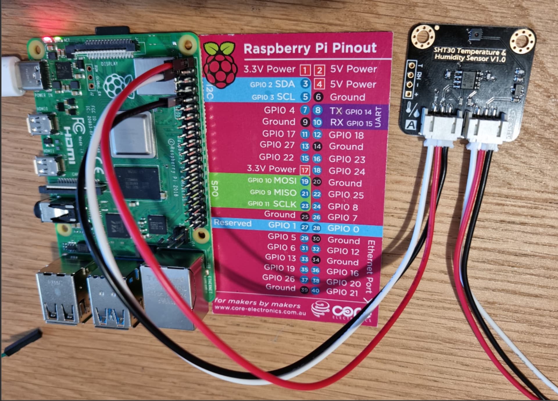
You should wire the sensor up to the GPIO in the following way: NOTE you need to use the standard GPIO pinout diagram. Print it out and stick it on your wall, you are going to be needing this constantly. Also to NOTE, GPIO Pin numbers are different to GPIO names, I have referenced the physical pin number.
Pi                            Sensor
GPIO PIN 1                    VCC
GPIO PIN 6                    GND
GPIO PIN 3                    SDA (NOTE THE ORDER IS REVERSED ON THE SENSOR TO THE PI)
GPIO PIN 5                    SCL (NOTE THE ORDER IS REVERSED ON THE SENSOR TO THE PI)
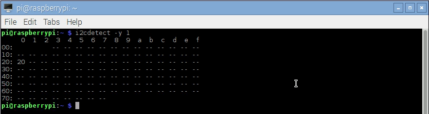
type: i2cdetect -y 1
and you will get an output telling you the address of the sensor that will look something like this
Save the following code as ‘sht31.py’ file but make sure to adjust the I2C address to what your sensor read in the above.
import smbus
import time

# Get I2C bus
bus = smbus.SMBus(1)

# SHT31 address, 0x44(68)
bus.write_i2c_block_data(0x44, 0x2C, [0x06])

time.sleep(0.5)

# SHT31 address, 0x44(68)
# Read data back from 0x00(00), 6 bytes
# Temp MSB, Temp LSB, Temp CRC, Humididty MSB, Humidity LSB, Humidity CRC
data = bus.read_i2c_block_data(0x44, 0x00, 6)

# Convert the data
temp = data[0] * 256 + data[1]
cTemp = -45 + (175 * temp / 65535.0)
fTemp = -49 + (315 * temp / 65535.0)
humidity = 100 * (data[3] * 256 + data[4]) / 65535.0

# Output data to screen
print ("Temperature in Celsius is : %.2f C" %cTemp)
print ("Temperature in Fahrenheit is : %.2f F" %fTemp)
print ("Relative Humidity is : %.2f %%RH" %humidity)
Type this from the command line: sudo python sht31.py
You will get an output similar to this:
$ sudo python sht31.py
Temperature in Celsius is : 26.52 C
Temperature in Fahrenheit is : 79.73 F
Relative Humidity is : 55.24 %RH
That will give you the ability to read the sensor.
Just as a follow up, if you were using Arduino then the code and execution to read either a digital or analogue SHT3X would be FAR easier.
I use one for my dew heater and the code was an absolute doddle for arduino, and there are loads of code examples online for it.