This is a placeholder topic for “Dual Digital Display DC Voltmeter & Ammeter 0-100V 0-100A” comments.
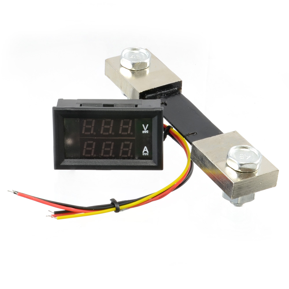
An all in one solution for monitoring voltage and current.
Read more
This is a placeholder topic for “Dual Digital Display DC Voltmeter & Ammeter 0-100V 0-100A” comments.
Hi. I was hoping to use this to monitor a salt cell on a pool chlorinator but that occasionally reverses polarity to clean the cell. Do you know if this meter will simply not display if the polarity is reversed or could it be damaged? I would power the meter from a separate supply.
Hi Andrew,
Welcome to the forum! 
Unfortunately, it doesn’t appear that this ammeter is able to handle a reversed polarity. I don’t believe that it will damage it, as the majority of the current would be passing over the shunt which shouldn’t be an issue to reverse. However, it wouldn’t be an appropriate part for that situation. If you’re only monitoring the salt cell for a short time, then you should be able to use an appropriately rated multimeter for that application. If you’ve got any further questions please let us know, enjoy your day!
Thanks for the info. I’ve used a multimeter for one-off measurements, was hoping for something I could leave hooked up. Not to worry.
Hey Andrew,
Do you know how many amps will be running through the wires?
I would check out these two boards to see if they would work for you application:
Liam
Hi. I’d like to use this unit to monitor the output of a 12V 12.5A power supply which I’m using to power and control a room full of LED lighting. The voltage should remain constant but I’d like to monitor the current over the full 12.5A range. The meter would have to draw its power from the same supply as the load, effectively connecting the two red wires together at +12V. Is this doable with this meter? I’ve added a modified version of the Wiring Option One picture to illustrate what I’m talking about.
Hi Bert
Don’t see why not as long as the voltage does not exceed 30V.
As a point of interest some of these meters of this type self power. I have one which has 2 wires to connect to power source and 2 wires that connect to load. There is also provision to power the meter itself externally but only required when the source is below about 5 or 6V (forget the exact figure off the top of my head).
Cheers Bob
Thanks Bob.
You’ve reassured me that I won’t let the magic smoke out!
Awesome. 
Bit of an old thread but I’m not sure that the wiring diagrams are correct - normally the two pin connector with red and black wires go across the shunt and the 3-pin connector is the power supply (thin red and black 5-30V) with the yellow being the load supply voltage measurement input (0 - 100V).
Hi Steve.
I think if you wire EXACTLY as outlined in the examples that come with the device you will have no trouble.I have used a couple of this sort of thing with no bother.
I think that is wrong for a start. The shunt is in series with the negative supply and the voltage drop across it is the drop caused by current through it. If this is the voltage measurement it connects across the supply as shown. The black wire is internally connected to “com” so with the connection shown i snot needed.
The circuit shown is for a high current version of this device. Up to a limit (10A I think) the shunt is not used and the current is sensed with a Hall device in the negative line. At higher currents the shunt is used to do what the name implies, shunts some current b across the hall device so there is always the 10A (I think) maximum through the Hall device. All carefully arranged so the Hall current is the correct proportion of the total and the reading scaled up in proportion to display the total (Hall plus shunt) current correctly.
Cheers Bob
OK - I see where the confusion is: The diagrams posted by Bert which I am referring to are applicable to a different device (as are your comments) and not the Dual Digital Display DC Voltmeter & Ammeter 0-100V 0-100A under which these comments are posted.
Hi Steve
My apologies. I did not look at the start of this thread. Bert is indeed referring to a different product.
You are right, the thick Black and Red wires connect across the shunt. The yellow connects to power positive and measures the voltage in conjunction with power negative. In other words the voltage measuring part of the device is Yellow and thick Black. The current measuring is thick Black and thick Red via a Hall device. With the low current version the shunt is not used (as stated above) and 100% of the current is passed through the Hall device.
With the 100A version the shunt is used and arranged so that 10% of the current passes through the Hall device and 90% passes through the shunt. The display is scaled to read the correct total current.
The thin Black and Red wires supply power to the electronics. If using in a self powered mode the thin Red connects to supply Pos and the thin Black is left disconnected as connection between thin and thick Black is common. In this mode voltage measurement is restricted to I think max 30V and min 4.5 to 6V. If measurement outside this is required the electronics have to be externally powered and the thin Red and Black wires are connected to this external supply.
I hope this sorts out any confusion.
Cheers Bob
Hi @Steve209327, Welcome to the Forums!!!
Thanks for pointing that out. It does look like that wiring diagram is for a different meter device.
The same idea of using the load as the power as the supply for the meter still holds true. just the wiring is different to that diagram.
And you can get our latest projects and tips straight away by following us on:
![]()
![]()
![]()
![]()
