This is a placeholder topic for “Gravity: 360 Degree Rotary Encoder Module” comments.
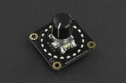
This is a cascadable 360 ° rotary encoder switch with 20 PPR, and each pulse corresponds to a detent. There are LED lights set for each detent to allow…
Read moreThis is a placeholder topic for “Gravity: 360 Degree Rotary Encoder Module” comments.
This is a cascadable 360 ° rotary encoder switch with 20 PPR, and each pulse corresponds to a detent. There are LED lights set for each detent to allow…
Read moreHi, does this encoder work with the adafruit/Adafruit_CircuitPython_seesaw library? I’m in ozzy, so would rather buy from you than the US. Thanks, Gis
Hi Giscard
Welcome
This product has its own Arduino library available via links on the Wiki page here
I think the “Seesaw” is a dedicated system for the Adafrut (I think) encoder breakout. You have to fit your own encoders. Core seem to have discontinued these, I could not find them just now. I bought a couple to fiddle with. They work well with no sign of bounce but are a bit slow to recover positional information.
Cheers Bob
Thanks for the reply Bob.
I’ve ordered 2 of all the options, DfRobot, Adafruit with the Neopixel and some standard Alps ones without anything.
I pretty new to this and have done a few arduino projects, but am (for now) sticking to circuitpython. So that limits some selections but also makes it a bit easier to make things actually work. Debounce issues being a big one. So not having to deal with that is a real plus.
Have a great week!
Hi Giscard
Yes, doing nothing about de-bounce makes for a pretty unusable device. Core have an encoder on a little board with some de-bounce filtering included on it which works pretty well. I have done some experimenting with this problem for a while and come up with some results I will publish shortly. I found this little board can be improved with a schmidt trigger buffer but in a lot of cases this is not required.
Some of my experiments here using that device
When you consider the operation of a rotary encoder in practise you will rotate the knob until you arrive at the desired result. Does it matter if there are a couple of counting errors along the way. I think not. If you go too far just back off a bit. It is when you get continuous large errors that it becomes really frustrating and if bad enough unusable.
I don’t know what the advantages of the ring of LEDs showing the position are as every time you start up the count will be zero. Looks good cosmetically I suppose.
Cheers Bob
Interesting!
I’m going to use the ring as a status indicator ‘traffic light” as it runs through the startup and standby sequences on an amplifier.
Thanks for the update.
Hi Giscard,
Welcome to the forum!!
I can confirm with Bobs findings that the two libraries wont work together (without some modifications).
The application for the LED ring sounds awesome!
We’re keen to see this project come together, we’d love to see some photos of it, or consider sharing your write-up: Create a Project Australia
Liam
How is it different from the one used here?
Hi Giscard
Interested to see how you are going to get access to the LEDs/LED drivers without hacking the board.
Cheers Bob
Hi Rooppoor212784
The device in your link seems to be a bare encoder with (I assume since there is a connection for VCC) pull up resistors fitted. There is no mention of de-bounce filtering so I don’t know how it performs. I might lash up an encoder with what I think is the configuration and try it.
The subject of this thread has an I2C interface and all sorts of other clever bits including the ability to read and store encoder information ad drive the LEDs.Taken care of I suppose via the library. The Adafruit Seesaw device mentioned earlier seems to take care of switch de-bounce so I suppose this one will do the same.
Cheers Bob
Hey Rooppoor,
Bob is absolutely dead on with his answer here, it looks like that encoder module doesn’t have all the extras that SEN0502 has. Its just a raw encoder module that has standard outputs compared to the i2C capability that can be found on this DFR module.
Hopefully Bobs tinkering may be able to give a solid answer on this one, as he is definitely a wealth of knowledge surrounding encoders. Something we have all appreciated in past here at Core Electronics.
Cheers,
Blayden
I have tried a bare encoder with just pull up resistors using the sketch in that link you provided and as expected the results were very erratic. In other words all over the place.
I then tried the sketch with the Core supplied CE09436 breakout which has filtering components on board. Refer the link above to my previous post. The results were as stable as previously but that sketch did not suit the encoder used. The sketch monitors the state of the “A” switch. The encoder I used has 2 “A” switch states per detent thus counts twice. Other than that the outcome is stable.
From this I would think this item you linked has some on board de-bounce filtering.
Some rotary encoders have 2 detents per switch cycle (mine have 1) and thus only 1 “A” switch state change per detent. I think this sketch has been written for such an encoder.
Cheers Bob
And you can get our latest projects and tips straight away by following us on:
![]()
![]()
![]()
![]()