Hi All
The onward saga of Rotary Encoder hardware bounce filters.
I recently discussed a system using the Core unit CE09436 with RC filters on board driving a rail to rail OP Amp configured as a Schmidt Trigger. I have just noticed on this I may have got the “A” and “B” switches mixed up. It doesn’t matter, if it counts the wrong way just reverse the connections.
This is a filter system using a bare encoder (I used a Bourns PEC11R series) and a Quad 2 input Nand gate HEF4011B (which I just happened to have) configured as 2 latching flip flops.
The original concept is to de bounce a SPDT switch where the switches latch the flip flop at the first transition and ignore any further transitions, bounces or noise until that switch releases and the other switch makes. Works very well. Claimed to be the ultimate de bounce circuit.
The problem here is the encoder switch is only ST (single throw). Would be nice if the other contact is there but it isn’t. I have simulated this with a FET (2N7000) which is switched by the opening of the SPST switch and the Gate going high. A Bipolar transistor is no good here as the base will only be 0.6V above ground at switch on d the “A” input of the gate needs to go fully HIGH (VDD).
The modified circuit follows.

To replicate the second switch pole the Q1 (Q2) switch-on needs to be delayed until the “A” (“B”) switch releases. This is done with R5 (R6) and C1 (C2). If this is not done the switch bounce and FET switching are operating together and proper latching and thus filtering is not achieved.
The output is taken from Q bar or Not (!) Q to follow switch action ie; LOW when switch closed, HIGH when open.
The values of R (5k1) and C (0.1µF) seem to be OK for “normal” finger rotation of the Encoder.
Oscilloscope pics using 5V

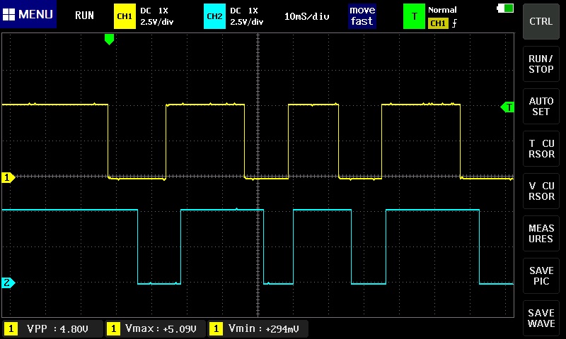
As you can see the IC is quite happy at 3.3V


I used this simple decoding and reporting sketch. For comparison purposes this is the same sketch used in the Schmidt Trigger circuit previously. No delays or other filtering in the sketch at all.
#define enc_a 2
#define enc_b 3

volatile int encoderValue = 0;


void setup() {
  // put your setup code here, to run once:
  Serial.begin(9600);

  pinMode(enc_a, INPUT);
  pinMode(enc_b, INPUT);
  attachInterrupt(digitalPinToInterrupt(enc_a), encoder, FALLING);

}

void loop() {
  // put your main code here, to run repeatedly:

}
    void encoder() {

      if (digitalRead(enc_a)== digitalRead(enc_b))
        {
          encoderValue++;

        }
        else
        {
          encoderValue--;

        }
      Serial.println(encoderValue);

    }
To test I spent about 15 min rotating the encoder one full revolution (18 pulses) clockwise then back CCW to start and recorded readings of 18 and 0 every time.
There is another IC available 74HC132 which has Schmidt Trigger inputs. This should provide another layer of reliability. When I get near a Jaycar or similar store I will get a couple to try. Slightly different pin connections but not a problem.
Will report results. Watch this space.
Cheers Bob
EDIT:
Sketch. As presented encoder counts down when rotating CW. To reverse this change equals (==) in comparison line to not equals (!=).
Further testing reveals an error of 1 digit very occasionally when rotating 1 full turn CW then 1 full turn CCW. happens about every 4th or 5th turn. Will retest with 74HC132 IC in the next couple of days. Could even be my rats nest wiring.