Looking for help to workout what and how to control the backlight of the Gravity LCD1602 blue V1.1.
Using the dfrgblcdpy python library I continually trigger errno 121 when writing to the chip/device with the RGB i2C address 0x6b. First call would be through self.bus.write_i2c_block_data.
I have tested other libraries, same result with no backlight light activation.
I assume Power (5V) and wiring to the module is good as the LCD will display text when using functions referencing the 0x3e LCD address.
Has anyone had a similar issues?
Should I be using both addresses, one for the LCD and RGB or just the LCD address? What I’ve lookup so far is not conclusive and contradictory. (could be just be my knowledge…)
Should I stick with it and try to resolve the error when referencing theRGB address?
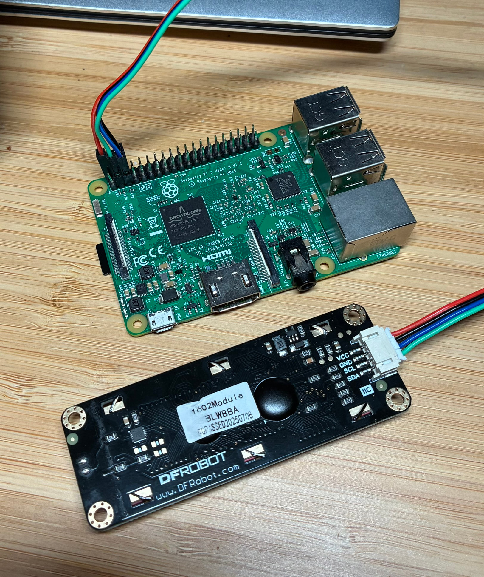
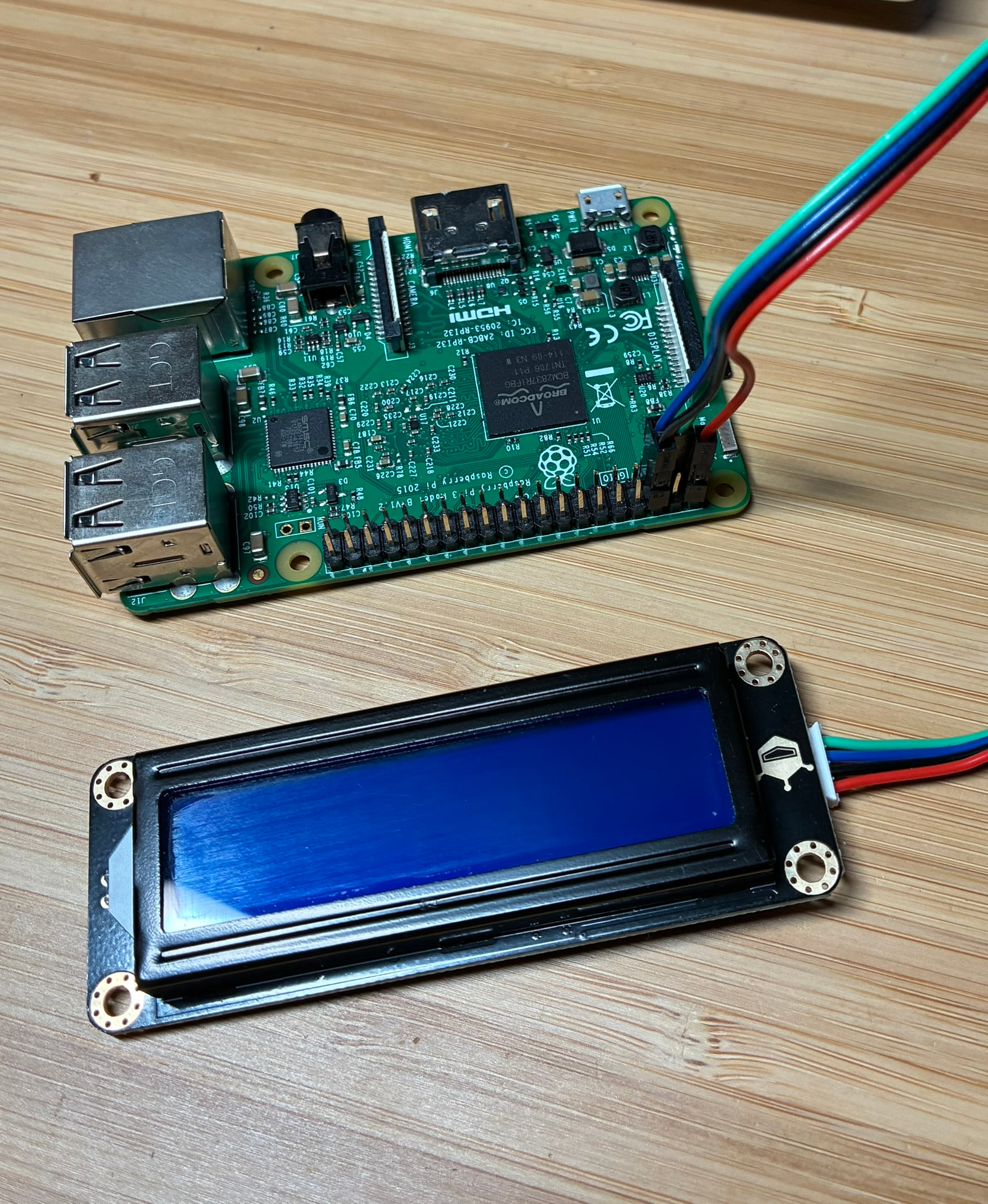
Thanks for reaching out @Jane . Pics attached, simple setup as I am testing the LCD module before adding to my next project. Looking forward to solving this one! 50/50 on user error at the moment. I should add - Using an rpi3 with the latest 64 bit OS installed, smbus for i2C comms.
As an additional test, I swapped out the LCD1602 module with a new Gravity I2C Digital Wattmeter. Same rpi3, OS and smbus comms and everything works well. No issues connecting and reading data from the sensor.
Scan attached. Text will display as the code uses 0x3e to update display. When the code try’s to use 0x6b for backlight/RGB control, this is when error 121 gets triggered. I have the blue version of the module. Some information sources say to use the 0x6b address for basic backlight on/off control with V1.1, other sources say you don’t need to. Hence the confusion.
So, going through the code with some handy print troubleshooting, I have found that the code immediately crashes the moment anything is assigned to the address register when using dfrgblcdpy’s library.
You mentioned that you have used other libraries with similar effects. May I ask what happened when you used the DFR LCD1602 library from the DFR Wiki?
Yes, that is where I started. This library uses wiringpi for i2c comms. Wiringpi needs to be installed as it is not part of the standard OS download from rpi as it is marked as deprecated. I did install wiringpi and ran the example code only to find that wigingpi needs to identiy the rpi hardware and where it looks in the current file structure is no longer valid in new version of the rpi OS.
There didn’t seem to be an easy way past this point so I moved to a library with smbus i2c comms. From memory the dfrgblcdpy.py was also recommened from DFRobot. For i2c comms, smbus is current and wiringpi is deprecated and at some point will no longer be supported. (functionality of the two libraries looks the same just different i2C comms package)
The next best library was RGB1602 which works well for text dispay and control but no luck controlling the backlight. Again it seems the LCD registers at 0x3e are ok but RGB registers at 0x6b do not respond. In this case, error 121 was not triggered when when writing to 0x6b, just nothing changed on the LCD display.
I did a little more digging and the wiringpi version I that came through the pip install was 2.5. There are newer community maintained versions of wiringpi with the latest being 3.16. I’ll try and get this installed as it may take care of this issue for newer OS versions. In the end though, I would like to think the LCD module would work with smbus like the Watt Meter does, also from the Gravity range.
I started going down a rabbit hole fixing compatibility issues that are far from the original project scope. I wasted a lot of time doing this setting up Grove boards and devices with legacy OS’s and libraries. Painful experience, hence the move to Gravity devices. Considering I now have the following Gravity sensors working on smbus i2c, from DFRobots libraries:
Watt Meter
ADC Module
Enviro Sensor
I’m no longer working on getting wiringpi to work as the i2c comms option. I will wait unitl a solution can be found with smbus or equivalent supported comms packages. If I need more LCD’s before then, unfortunately I will look at another brand offering.
Question / Request though? Does the Python DFRGBLCDpy libary actually work with the LCD1602 RGB module? I’m not a bulk buyer so the extra few dollars per unit is manageble. (However I would still like to get the Blue version working on smbus though)
Honestly, probably a good idea to jump away from it. Rabbit Holes always get wider the deeper you go.
I’ve yet to see the DFRGBLCD’s library work with the LCD1602 module’s backlight. Same as you we could get text to move across, but no backlight. It might be worthwhile posting an issue on the Github and seeing what they say:
I’m glad I avoided the rabbit hole and went back to the original problem. It seems I have found the issue……Looking at the first call to the RGB driver with address 0x6b, it faults on trying to write to a register that doesn’t exist in the data sheet of the RGB driver PCA9633 (This is the RGB chip used as per the gravity LCD1602 manual). Commenting out the call to write to this register cleared the error and the backlight now functions. (Line 320 in the _init_ routine)
Next step is to cross check what the data sent to registers 0x00-0x03 actually does and that nothing is missing from the setup process. On researching this error a little further, it seems at some point a different RGB driver was used on the PCB, IS31FL3193, which has a 0x2F register to write to as per its data sheet.
In summary, smbus comms work for backlight control, just check what RGB driver the PCB is using and does the setup code match.
Thanks for the support on this topic, we got there in the end!
Wow, that is weird. I noticed when I was testing the code that it wasn’t able to get past the first set_reg() call, but I assumed it was something faulty with the function, not that specific register.
I’m glad you figured that out. Hopefully the next person who stumbles across it will have a much easier time thanks to your troubleshooting.
Since the LCD shows text on 0x3e, your wiring and power are fine. This module uses two I2C addresses: one for the display and another for the RGB backlight, so both need to work for the backlight to light.
If the RGB address keeps giving errno 121, it’s usually down to initialization or a library mismatch with the V1.1 board. You should definitely try to fix that instead of ignoring the RGB address, the backlight won’t work through the LCD address alone. For some practical I2C display hardware examples that might help you understand how the backlight and controller wiring works, check out this PCBWay shared I2C LCD project: https://www.pcbway.com/project/shareproject/Diy_I2C_Lcd_Module_6032c75c.html