This is a placeholder topic for “Gravity: MCP23017 IIC 16 Digital IO Expansion Module” comments.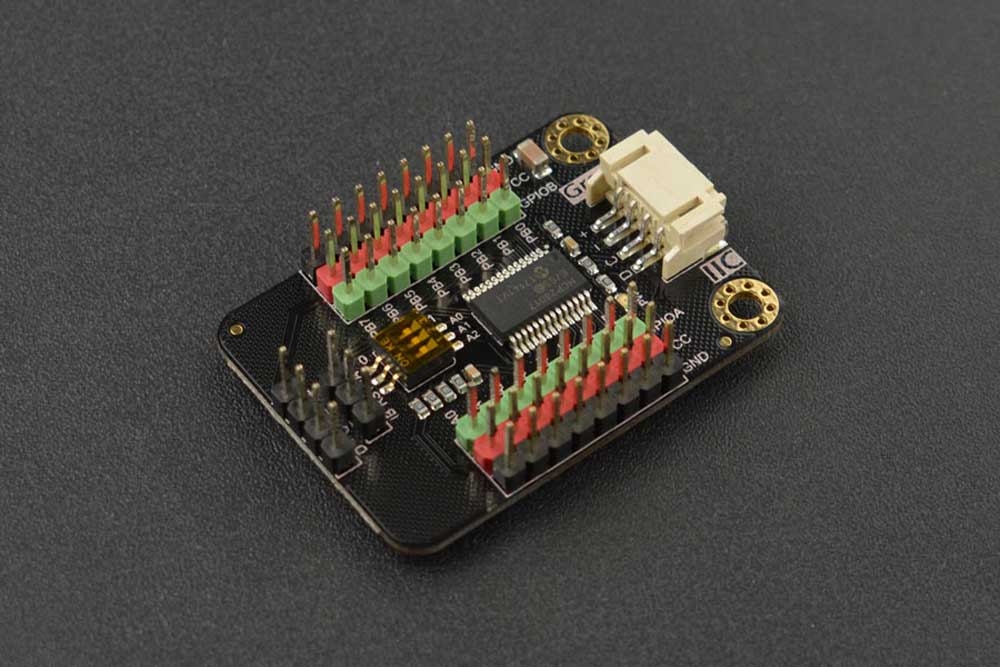
This is an IO expansion module that based on the chip MCP23017. The module can expand additional 16 IOs. It can set 8 IIC addresses, which means with this module, … read more
Read more
1 Like
I am having difficulty confirming my DFR0626 Expansion Board is working.
I have even resorted to running the Button Press sketch on the wiki.dfrobot.com site but cannot get a Button Press.
How else to test the board? Ground connected. 5V on VCC pins.
1 Like
Hi Anthony,
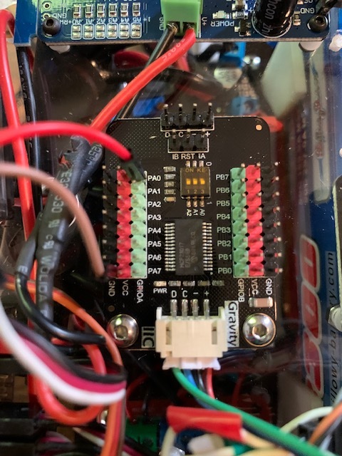
Welcome to the forum, can you please post a photo of your hardware setup? You never know what a second-set of eyes might pick out. Once we’ve double-checked all the hardware connections we can try replicating your setup here to see if we get the same issues running the same sample code.
1 Like
Hi Trent
Thanks for responding.
The button has 2 wires (change colour in photos) , one ground (on PA7), the other, signal on PA0.
The expansion board is connected to the IIC pins on the Sensor Shield V5
Regards


2 Likes
To confirm, is this the code you’re running? I can see in DFrobot’s comments that the pin GPA0 is set up as INPUT, and not INPUT_PULLUP. That would imply that you need to connect the other side of the button to VCC rather than GND to register a button press. If you swap that connection and re-run the script that ought to fix it.
Other thoughts
I personally don’t like this approach though, and much prefer the way you have wired the circuit up, with the button pulling PA0 to the ground. If you wish to leave the circuit like this, try changing this line
mcp.pinMode(/*pin = */mcp.eGPA0, /*mode = */INPUT);
to this instead:
mcp.pinMode(mcp.eGPA0, INPUT_PULLUP);
Of course, your switch logic is now inverted, so you’ll have to invert the logic that detects a button press eg.
uint8_t value = ~mcp.digitalRead(/*pin = */mcp.eGPA0); // Note the ~ (NOT) operator at the start of the line
If you still have trouble, perhaps we should simplify the circuit - just for testing. There could be an intermittent connection somewhere: What happens if you run the sketch and just connect PA0 to VCC (or ground) using a single jumper wire?
2 Likes
Hi Michael
Thanks for your help. Yes, that is the code I am/was running.
The board does indeed work.
Not only that, I re-introduced my DFR0576 multiplexor into the project and , , once again, communication with the button was successful.
As suggested, I changed the pinmode to INPUT_PULLUP.
I preferred an alternative to the ~ NOT approach, testing value==0 for a button press.
Thanks for introducing me to INPUT_PULLUP.
Regards
2 Likes
Hi
I have a further challenge using the DFR0626 Expansion Board and that is handling PWM values sent by a Spectrum AR8000 receiver.
I successfully handle these via Arduino Uno digital pins using code like this:
pinMode(pinAUX1, INPUT); // Flap/Arm Servo
ch4 = pulseIn(pinAUX1, HIGH, 250000);
int flapset = map(ch4, 1000,2000, -500, 500); //center over zero
flapset = constrain(flapset, -255, 255); //only pass values whose absolutes are
                                   //valid pwm values Flap0 = 255, flap 1 = (>10/<10 i.e. 0 +/- 10), flap 2 = -255
Attaching the signal cable from the AR8000 to the extender board port PA0, I am having trouble get any reaction to movement of the AR8000 flap switch using this code:
mcp.pinMode(/*pin = */mcp.eGPA0, /*mode = */INPUT_PULLUP);
 uint8_t valuemcp = mcp.digitalRead(/*pin = */mcp.eGPA0);
or
ch4 = pulseIn(mcp.eGPA0, HIGH, 250000);
Guidance appreciated.
Sadly I doubt you’ll be able to treat the extended IO exactly the same as you can the Arduino IO.
GPIO extenders are great for basic IO like buttons and LEDs. They don’t have the same functionality as the microcontroller’s GPIO however. You won’t be able to perform high-speed IO functions like frequency-measurement or pulse measurement with pulseIn().
2 Likes
OK
Thanks
1 Like
Hi Anthony,
If you’re looking to get some more PWM pins out of your dev board I would investigate using another MCU and setting it up as an I2C or UART slave.
There’s a bit of dev work involved but definitely achievable - I’d check out the Pico for a low cost microcontroller with lots of grunt!
Liam.
1 Like