I have made the esp32 device in the link below, and have compiled the ESPhome Builder YAML and loaded it to the device. The one thing I am unsure about is, what is the earth wire meant to be connected to? This is going in a fibreglass camper, so there is not really anything available that I would call an earth. I guess I could make something up to plug into the earth pin on the 240v plug, but that seems less than ideal. Any thoughts appreciated.
The purpose of this is for a dehumidifier that sits in a closed fiberglass camper. We are in a humid coastal environment, and I am trying to avoid rust buildup on hinges, and the other metal hardware in the camper. I currently have a 240v plug that automatically turns on every day for 30 minutes just to top up the battery. I want the esp32 to then be turned on, and trigger the dehumidifier to turn on. The dehumidifier has an overflow switch, which I will wire up to the ESP32 to notify me when the bucket needs emptied. I will also have a light sensor on the ESP32 to make sure the dehumidifier turns on, and notify me if it does not turn on. Just trying to retrofit “smart” to a “not-smart” device.
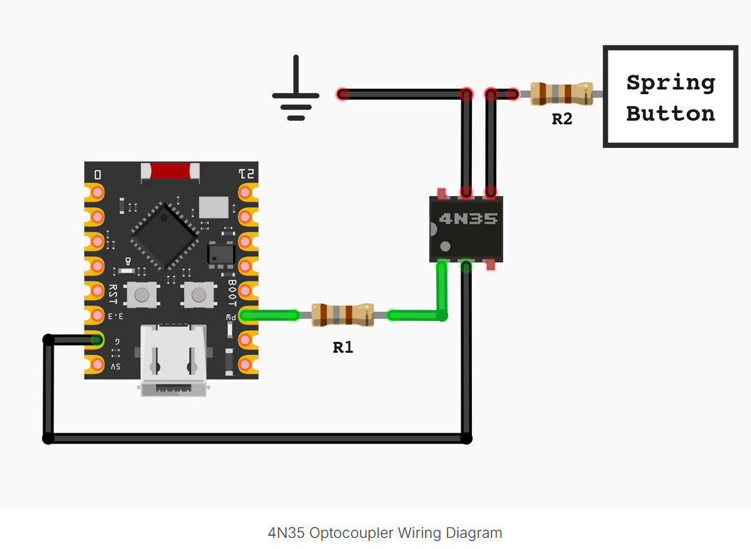
Your diagram doesn’t seem to make sense. A spring button would typically be used as a switch, so it appears that the part of your system this diagram refers to is the part that signals to the ESP that the bucket is full. But you have the switch connected to pins 4 and 5 of the 4N35, which is the ‘output’ side of the device.
I think your diagram shows the ESP controlling an existing spring button as a substitute for actually touching it. GPIO7 will control that device via the 4N35. That’s what the connection of the 4N35 to the ESP looks like.
If that’s what you are trying to do then pin 5 of the 4N35 will be connected to the high side of the circuit for that device, pin 4 will be connected to the low side of the circuit for the device, and the device itself will be somewhere in that circuit, either on the high side or the low side.
In that case the signal from the ESP will pull pin 5 to ground, which I think is what you want to do. So you have 4 and 5 the wrong ways around, and the ground that you would connect 4 to is the ground side of the spring button.
The main thing to remember is that earth and ground are different. Mains earth (green/yellow wire) is for electrical safety and doesn’t need to be connected in your ESP32 circuit. The ground in your diagram is just the 0 V reference for the ESP32 and 4N35, and that’s all you need here.
In your wiring, pins 4 and 5 on the 4N35 are swapped. Pin 5 should go to the high side of the button circuit, and pin 4 to the low side (ground). Double‑check the datasheet to be sure.
For safety, keep the ESP32 side completely away from mains wiring.
Just checking if I understand the circuit. It is not my circuit, I am just trying to monkey-see monkey-do on someone else’s implementation.
I am connecting this to a spring that is a capacitive switch on a dehumidifier. When I place my finger on or near that spring, the dehumidifier turns on or off. The way I understand it, I just need to supply some kind of capacitance change for this to work.
If I understand the circuit, when I supply a small current to the 4n35 Anode, then the emitter and collector go closed circiut? And the result of this in the circuit is to momentarily connect the capacitance spring to ground, thereby changing the capacitance and triggering the dehumidifier to turn on or off.
Tomorrow I will try it, connecting the collector and emitter to the capacitance spring and an outside tap as the ground to see if it works.
In trying to find some way to automatically trigger this dehumidifier, i found if I tapped a 1.5v battery on the plastic top of the dehumidifier (where the capacitive spring is), then it turns on or off. I thought about making a servo that taps the battery on the top! . But no moving parts is the better option.
Thank you for clarifying which part of the project applies to the circuit you provided.
Triggering a capacitive switch is going to be different than triggering an ordinary mechanical switch, so it likely needs to be implemented differently. If the circuit you provided is designed to provide some sort of capacitive loading to the switch then perhaps it is supposed to be wired like that, but in that case I would have no idea what the connection marked with the earth symbol should be connected to. The description implies that it connects to the switch, but the schematic shows the other end connected to the switch, and there is no mention of two connections to the switch. The output of the 4n35 is being used in a very non-standard manner, and the only likely way to answer your question is by experimenting.
If you swap the connections to the 4n35 as mentioned above then the signal from the ESP will cause the connection at pin 5 to drop to ground from whatever potential it is held at by the switch. That would be similar to a capacitive effect, where the current needed to charge the capacitance would create a momentary drop in the voltage. But whether or not that is how the circuit is designed to work, and whether or not the switch would work like that, is anyone’s guess. I note that the article you reference does not have any responses from someone who actually used this circuit.
Hi Jeff.
If one side of the capacitive switch is connected to “Ground” and there is a concern about taking the “hot” side of the switch directly to this ground there is a way out.
Connect a capacitor of about 10n or 100n (not critical, might have to experiment) to the “hot” side of the switch. Connect the other end of the cap to the 4N35 in such a manner that it pulls the “low” side of the cap to ground. The cap will ground the high side of the switch momentarily the same as putting your finger on it. You need to connect a resistor of about 50kΩ across this cap to discharge it ready for the next signal. That way you could operate this switch automatically via the 4N35 or manually as normal with a finger.
Cheers Bob