Help needed with Sparkfun u-bloc sara board

Hi All,

Firstly thank you for the support. I have purchased a SparkFun LTE GNSS Breakout - SARA-R5 board with the idea to send a text message from an esp32. I have successfully powered up the Sara board with a 5v dc dedicated power source and the lights are on. The Sara board powers on and off, power button works with the power light going off/on. My concern and ask for support is how to communicate with the board. I have the RX and TX connected but no serial response or output in Arduino. I have tried swapping the RX/TX and still no output. I would like to start with simple test to get SARA board information but even using the examples no success. Any help would be great. Also I am new so please be patient with me. David.

1 Like

Hey there, @David195253,

Can I please confirm that you have opened the jumpers on the underside of the board?

By default, those pins will be passed through the USBs and need to be cut so you can isolate and interact with them. More information in the hook-up guide:

My board looks the same as your picture. For noting, I have connected the RX and TX to RXD0 and TXD1.

1 Like

Hey @David195253,

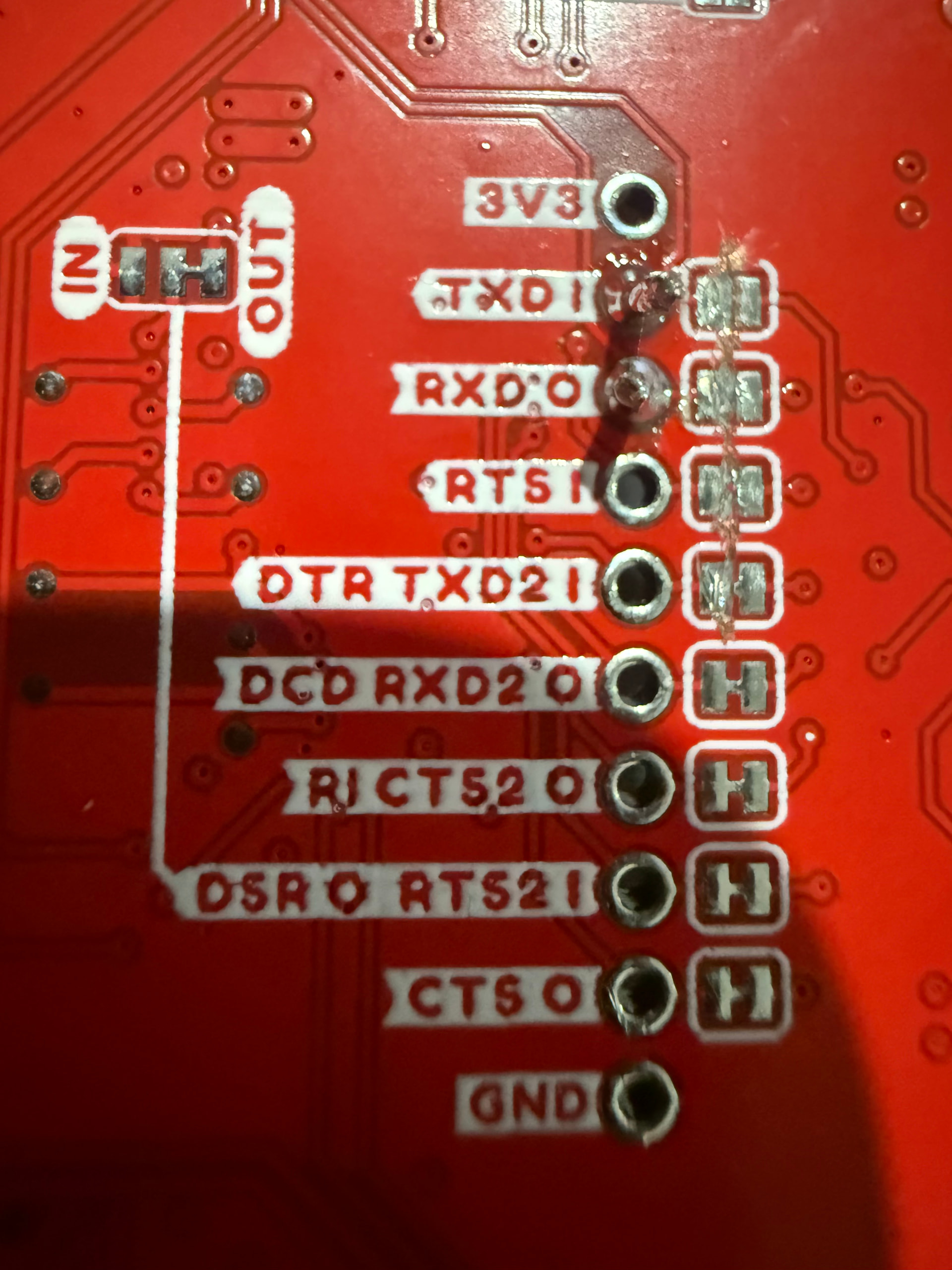
That’s fine, I was asking whether you had cut the tracers beneath RXD0 and TXD1 to open the lines. Because otherwise those pins are closed in their default state.

image

Hi Jane, not cut.

1 Like

No worries, @David195253, then opening those jumpers would be the next step to facilitate UART connection via those pins.

Thank you for the help, is there a document which describes this so I can do some reading. I will cut the two joins for RX and TX and come back with results.

1 Like

No worries, David, it’s all laid out in the Hook-up Guide on Sparkfun’s Learn platform for this product.

Just to be clear all of the jumpers need to be removed? I ask because I just removed the two (RX,TX) and it still does not work

1 Like

Hi there, @David195253,

Only the TX and RX Jumpers need to be cut for it to work. Would you be able to upload a photo of your board and how you interacting with it? It would make it easier to offer support.

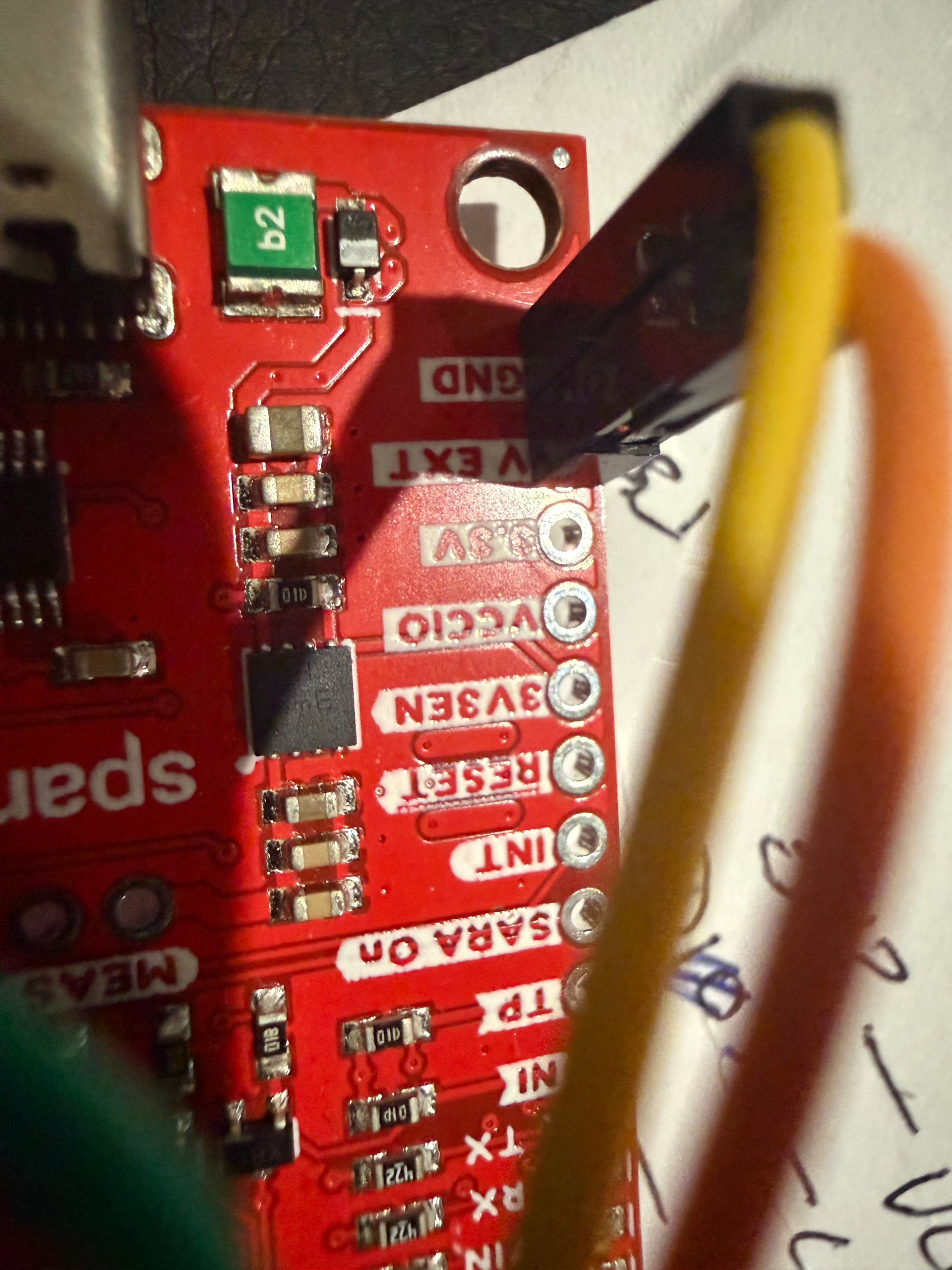
Hi Jane, apologies for the delay in my reply. I have attached photos of my setup. I have 5V and GND from the ESP32 Micro to the Sara board. The Sara board power up with lights on. I have the RX and TX going to the right pins on the ESP32 board. I have cut TXD1, RXD0, RTS1, DTR TXD21.

1 Like

Thanks for that, @David195253,

Could you please confirm which of your LEDs are lighting up on your board?

If the RX and TX are correctly connected than their corresponding LEDs should be lighting up on the side. I would also recommend tidying up the solder on the TXD1 which doesn’t look quite as well connected as it’s neighbour.

Also, could you please confirm the make of your microcontroller? It would be useful to triple check the pin outs for the board.

Hi, The solder on RX and TX is good as attached, along with the board powered. The RX and TX does not light at all. David.

1 Like

Hi David
The TX and RX LEDs will only light up when there is Data traffic on the circuit. Even then it will only be brief flashes corresponding to the HIGHs (or LOWs depending on actual circuitry). Similar to the TX and RX LEDs on an Arduino when communicating such as loading a sketch or similar.
Cheers Bob

1 Like

Bob is right, hence why I asked you to tell us your microcontroller’s name so I can confirm pin out has been configured correctly. In addition, could you upload the code you are using to flash the SARA? With both of those bits of information, we can determine if the serial communication has been set up correctly on the microcontroller.

The circuit is using an xiao esp32-c3, which is connected via the USB to my laptop.

The ESP32 is connected to the Sara board:

  • Power via the 5V and GND to the Sara board V_EXT and GND
  • GPIO4 RX to Sara TX
  • GPIO5 TX to Sara RX

The ESP32 is programmed using Arduino. I have tried the following:

#include <HardwareSerial.h>
HardwareSerial saraSerial(1);
// XIAO ESP32-C3
#define SARA_RX D2 // connect to SARA TX
#define SARA_TX D3 // connect to SARA RX

long baudRates = {9600, 19200, 38400, 57600, 115200};
int baudIndex = 0;
unsigned long lastSend = 0;
unsigned long lastSwitch = 0;

void setup() {
Serial.begin(115200);
delay(1500);
saraSerial.begin(baudRates[baudIndex], SERIAL_8N1, SARA_RX, SARA_TX);
Serial.print("Testing baud: ");
Serial.println(baudRates[baudIndex]);
}
void loop() {
while (saraSerial.available()) {
Serial.write(saraSerial.read());
}
while (Serial.available()) {
saraSerial.write(Serial.read());
}
if (millis() - lastSend > 2000) {
lastSend = millis();
saraSerial.print(“AT\r”);
}
if (millis() - lastSwitch > 8000) {
lastSwitch = millis();
baudIndex = (baudIndex + 1) % (sizeof(baudRates) / sizeof(baudRates[0]));
saraSerial.end();
delay(200);
saraSerial.begin(baudRates[baudIndex], SERIAL_8N1, SARA_RX, SARA_TX);
Serial.println();
Serial.print("Testing baud: ");
Serial.println(baudRates[baudIndex]);
}
}

With Sara on, Result I get

21:36:44.830 → Testing baud: 9600
21:36:52.823 →
21:36:52.823 → Testing baud: 19200
21:37:00.843 →
21:37:00.843 → Testing baud: 38400
21:37:08.831 →
21:37:08.831 → Testing baud: 57600
21:37:16.841 →
21:37:16.841 → Testing baud: 115200

but if I press the “SARA On” button to turn it off I get

21:38:44.872 → Testing baud: 9600
21:38:44.933 → ����
21:38:52.843 → Testing baud: 19200
21:38:52.925 → ��y_�y��y�
21:39:00.837 → Testing baud: 38400
21:39:00.905 → AV�aV�aV�aV�
21:39:08.866 → Testing baud: 57600
21:39:08.936 → AT�AT�AT�AT�
21:39:16.841 → Testing baud: 115200
21:39:16.915 → ATATATAT