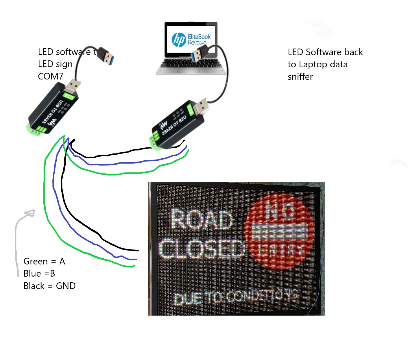
I’m trying to get the serial communication that goes from my LED software on my laptop to the LED sign so I can use it through a raspberry pi, bypassing the LED software. The LED sign uses RS485 and the software is LedCentreM6.00. I’m using a USB-to-RS485 by Waveshare (Industrial USB to RS485 Converter | Buy in Australia | WS-17286 | Waveshare | Core Electronics) to go from the laptop to the sign. The software is not Linux compatible. The laptop I using is running Windows 10. The baud rate of the sign is 115200. The sign using Hexadecimal.
I’m not sure how to use PuTTY as you can’t use it to sniff a port (say COM7) if it is being used by another program.
I thought maybe using HxD to interpret the *.lpp, *.lpl, and *.rsf files that come from the software that should contain the serial instructions I need. I haven’t tried this yet, as I need IT to install programs here at work - I don’t have admin authority.
Anyone have any other ideas, or could add to my suggestions to make it work?
Checkout Portmon by SysInternals. They were bought by Microsoft so it’s official Microsoft software now. Should help with sniffing the serial communications.
RS485 is more the physical layer sends the serial data. As already mentioned, their will be the comm port settings.
I would use a from of logic analyzer, something like
should be ok (just need to check the RS485 voltage levels v the max input voltage to the analyzer (that one looks to be 5.25V max).
this will give you the full “RS485” bits either correct or inverted (depending on which pin you monitor and the analyzer software decoder settings.
So, if you have 9600 Bps, 8 Data bits 1 start 1 stop and no parity, then you would see 10 bits per byte sent, and the decoder should be able to output the raw bytes.
While you can get software port monitors for different OS, it means its locked to devices that connect to that PC, a logic analyzer is also nice to have when debugging lots of things.
edit
Example of that analyzer and pulseview (free software)
In theory something like that can work. Just keep in mind that the comms may or may not be text based, so when logging you will want to save “all session output” and may need to view in a binary/hex editor.
You will need to ensure the comms settings are the same.
RS485 is half duplex, so the same wire is used for TX and RX, so if the comms is bi-directional, it may take some analysis to work out the back n forth…
You have a display panel that uses a Windows program called LedCentre to control it.
You want to do some thing that the software does not provide, although I found a manual for LedCentre and it looks quite comprehensive.
so…
Can you explain further what you want to do e.g. display some different graphics not available in the software?
Can you work with the Software Developer to add features or are you trying to replace it ?
Have you looked up the details of the display panel to see what commands it uses? Often devices have a FCC registration that will point you to the OEM or some more technical information. Can you open the display and see what control board it uses?
I’m trying to use the Rpi to send the sign ‘instructions’ without the software. Eventually creating an app for the sign that allows the user to open a road or close a road at the push of a button. First step it getting the Rpi (which will be the middleman between the modem and the control board) to control the sign. The first thing I tried was getting the LED software to send data to USB, then get the rpi ro send that to the sign. Didn’t work. So been tweaking the script without success so far. I used a free online program called HexEd.it to create a Hex file, but that’s as far as I have got so far.
I’m working on a script with Gemini’s help but it sends data to the sign, but the sign doesn’t respond. Here is the test script so far:
If I can get the Rpi to communicate and change the sign’s message, then I can work on the RockBLOCK (Iridium modem) ← → Rpi ,_ → LED sign, then the app.
I have downloaded Wireshark but haven’t installed and tried it yet. I tried PuTTY but it can’t monitor the port that is been used by the software, so I need another set of equipment to relay the message back to another port. Portmon won’t be suitable as it asks for admin permission every time and I don’t have admin privileges at work (where I doing this). Can Wireshark monitor a port in use by another program (ie the LED software)?
But yes I think I need to hijack the serial communication directly from the software because nothing else has worked.
While I haven’t use Wireshark specifically for serial ports, Wireshark’s whole deal is that it’s meant to listen into packets. If you use it on an idle Windows Computer, you will quickly see the shockingly large number of packets sent between your PC and Microsoft’s servers. So yes, it should be able to listen into a used by another program.
I need some way of capturing the communication through my COM PORT 7 (USB) that doesn’t interfere with the program. Every tool I have used either stops the program from using the port or doesn’t monitor USB ports
I have just looked into this a little bit more and it appears that while Wireshark works great with Linux, it doesn’t like Windows. Gotta love Windows.
What OS are you working on, I have been assuming windows?
edit:
On windows you need to have some sort of driver and some of the older tools like port mon dont seem to have 64bit versions, which at the driver level will be an issue.
I am a fan of device monitor studio, but its getting a bit $$ now but does exactly what you want to do. I think the standard version is now > $US150 so at the price and if you are into electronics I would rather buy a logic analyzer.
That said…
To monitor a bidirectional setup you need to have the main coms line you want to monitor, then TWO other serial adapters to monitor with.
If you want to use some USB-RS232 Adaptors, then you will need a hook up something like this
So
PC → USB/RS232 1 → Device/Display (TX/RX)
Then USB/RS232 2 → USB/RS232 1 TX
Then USB/RS232 3 → USB/RS232 1 RX
So then monitoring USB/RS232 2 and 3 should yield the raw data between the two. At this point you need to work out the best way to collect that data.
If its binary data, then best to collect it in HEX (somehow)
if its a text based comms, then putty should be fine (as long as everything is on the same comm settings)
Then installing software on the Company laptop is not an issue, just use Putty and log some stuff to a USB stick and analyse it at home with Wireshark on a personal laptop/PC.
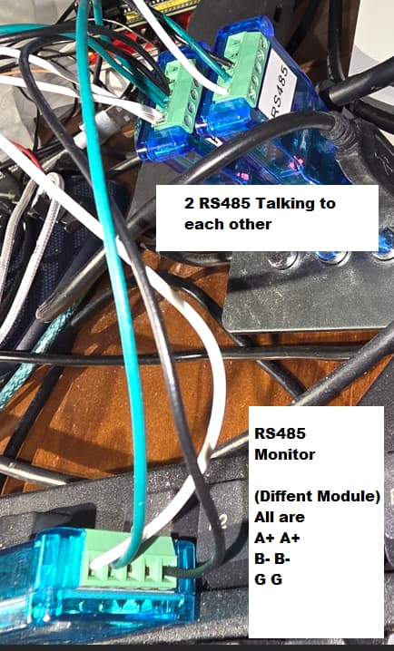
cheers I missed the 485, so that by default will be a 2 wire bus + ground, so connect A+ to A+ and B- to B- and ground to ground. As long as your USB adaptors are support the voltages (standards) then that would be a passive monitor in RX mode. then if its bidirectional where each end sends something (e.g. PC → Command … Dev ← Ack, you could see that in order via the one adaptor… Nice thing about a bus, easer to tap into .
Edit:
Sorry for the mess, I just wanted to do a quick demo for the RS485
Thanks people, I ended writing a script in python that does the job, albeit not as well or with the possibilities that the original software can do, at least at this moment. I’ll try and work on that in the future but for now I have a solution that gets the job done.