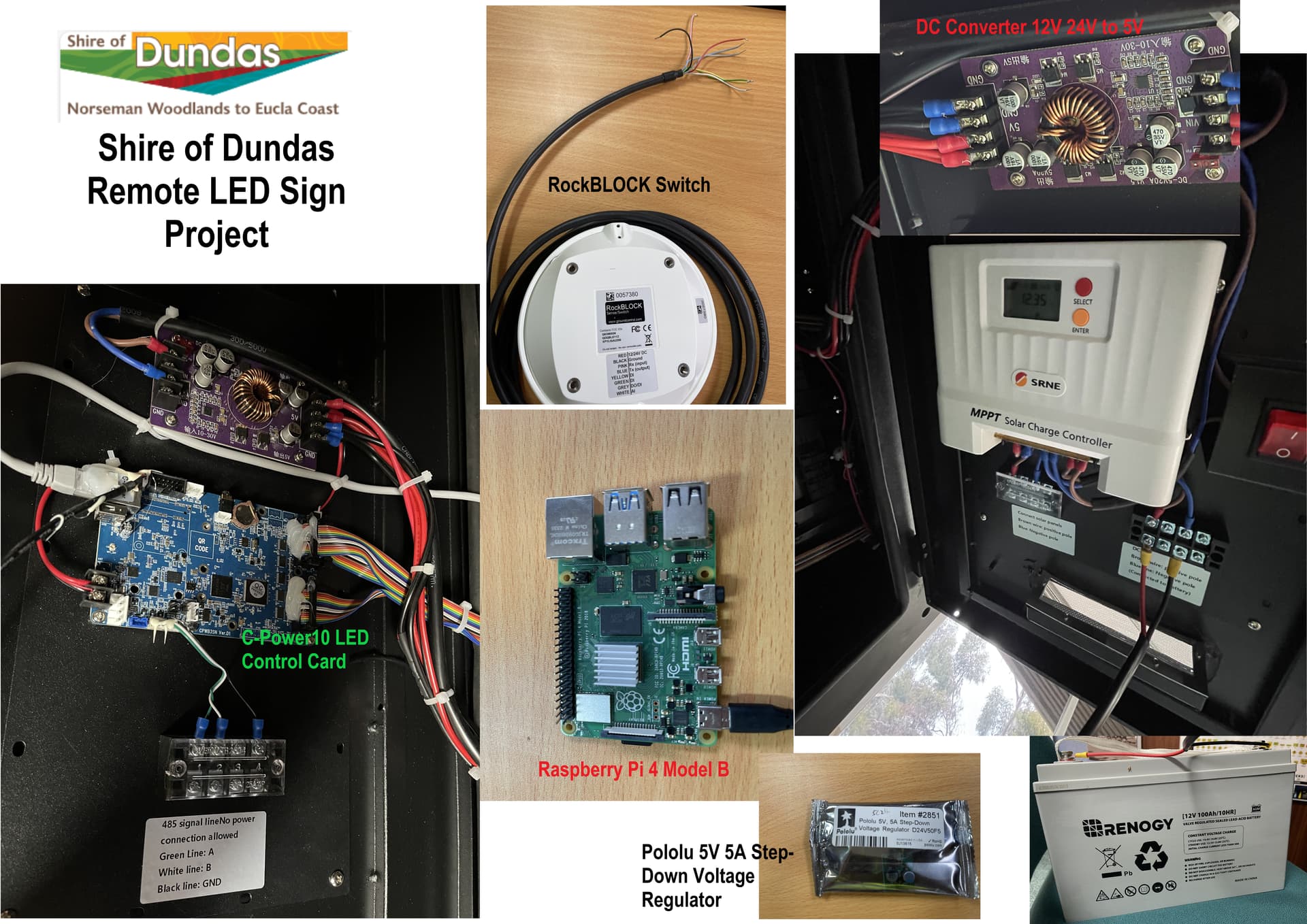
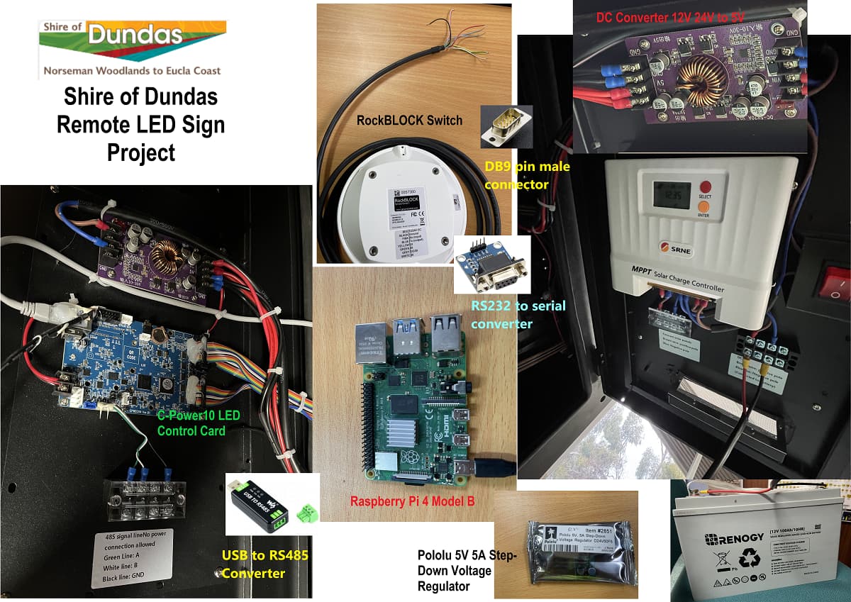
This is my first project. I have purchased a LED sign that uses a C-Power10 control card and has 485 signal line (A, B, GND). I also have a RockBLOCK Switch/Sense which I wish to control this sign in a remote location where I can only get a satellite signal. I also have a Raspberry Pi 4 Model B.
I’m making sure I get all the items I need. Gemini (AI) is suggesting I use a Bidirectional Logic Level Shifter for the RockBLOCK connection to the Raspberry Pi. The critical point here is the voltage mismatch (5V vs 3.3V) for the serial data lines.
It is also suggesting a DC-DC Buck Converter but I was going to just insert into the 5V converter in the sign. Any help would be appreciated.
You may need a logic level shifter, just confirm that the RockBLOCK is ouputting on 5V as AI can guess voltage outputs without actually checking. If you do need a shifter, than something like this would be suitable Bi-Directional Logic Level Converter.
If your LED sign provides a stable 5V supply with at least 3A current capacity, you may be able to power the Raspberry Pi directly from it. However, Pi 4s can draw significant current, and voltage dips during communication with the RockBLOCK could cause crashes or data corruption. If you have a 12V power source available, this buck converter is a suitable option
I got a reply from RB directly and here is their response:
The RockBLOCK Switch is an entirely different product from the RockBLOCK 9603 and 9602, with different connections and intelligence so we don’t want to merge those together otherwise it’ll get more confusing than it already can be! It sounds like what you’ll need is:
RBSwitch ↔ RS232-to-TTL level shifter or RS232 HAT/USB adapter ↔ RaspberryPi ↔ RS485 transceiver ↔ LED sign.
The USB/Serial converter is only needed if you want to control the sign using the USB port on the Pi. The Pi supports a UART interface, so it is possible (and simpler) to just do RBSwitch ↔ RS232-to-TTL level shifter ↔ RaspberryPi. The code will be the same.
The suggestion that you obtained was
RBSwitch ↔ RS232-to-TTL level shifter or RS232 HAT/USB adapter ↔ RaspberryPi ↔ RS485 transceiver ↔ LED sign.
Notice the ‘or’.
Your choice of the RS232 to Serial Converter and the USB/Serial Converter implied that you were doing both
RBSwitch ↔ RS232-to-TTL level shifter ↔ RaspberryPi
and
RBSwitch ↔ RS232 HAT/USB adapter ↔ RaspberryPi
My comment was that you don’t need the hat (the USB/Serial converter) because the Pi understands TTL UART just as well as it understands USB, so RBSwitch ↔ RS232-to-TTL level shifter ↔ RaspberryPi is the simpler option. The RS232 to Serial Converter you have listed above will do that job.
I am assuming that, as that was one of the options provided to you, the RBSwitch supports that connection. The actual wiring of the switch to a serial port of the serial/TTL converter is something that the supplier should be able to assist with (as it is their suggestion). The connection of the TTL side of the RS232-to-TTL converter to the Pi is something that we can help you with.
Thanks again Jeff, I think it have the RBSwitch to the RPi sorted, and now need the RPi to the LED sign connection sorted. The sign uses RS485 and if you look at the picture, you’ll see the control cards 485 connection points. Is this the sort of thing I need or do you have something else?
Thanks for your help people, I’m about to start testing the whole project. It’s all coming together but still a bit of work to go. I’m about to integrate the LED, Pi and the RockBLOCK and testing it. I’ve used this forum, Gemini AI (hopeless!), Claude ai (Great but crashed out on me due to limited use which I have exhausted), ChatGPT (Limited help, like Gemini, would usually make things worse LOL), CoPilot (was ok), and an expert Solutions Architect from GroundControl (the developers of the RockBLOCK). Pretty difficult when you have to do everything through emails and forums and working on your own, but patience and perseverance is paying off. Cheers people.