This is a placeholder topic for “Makerverse Real Time Clock (RTC) with Supercapacitor Backup” comments.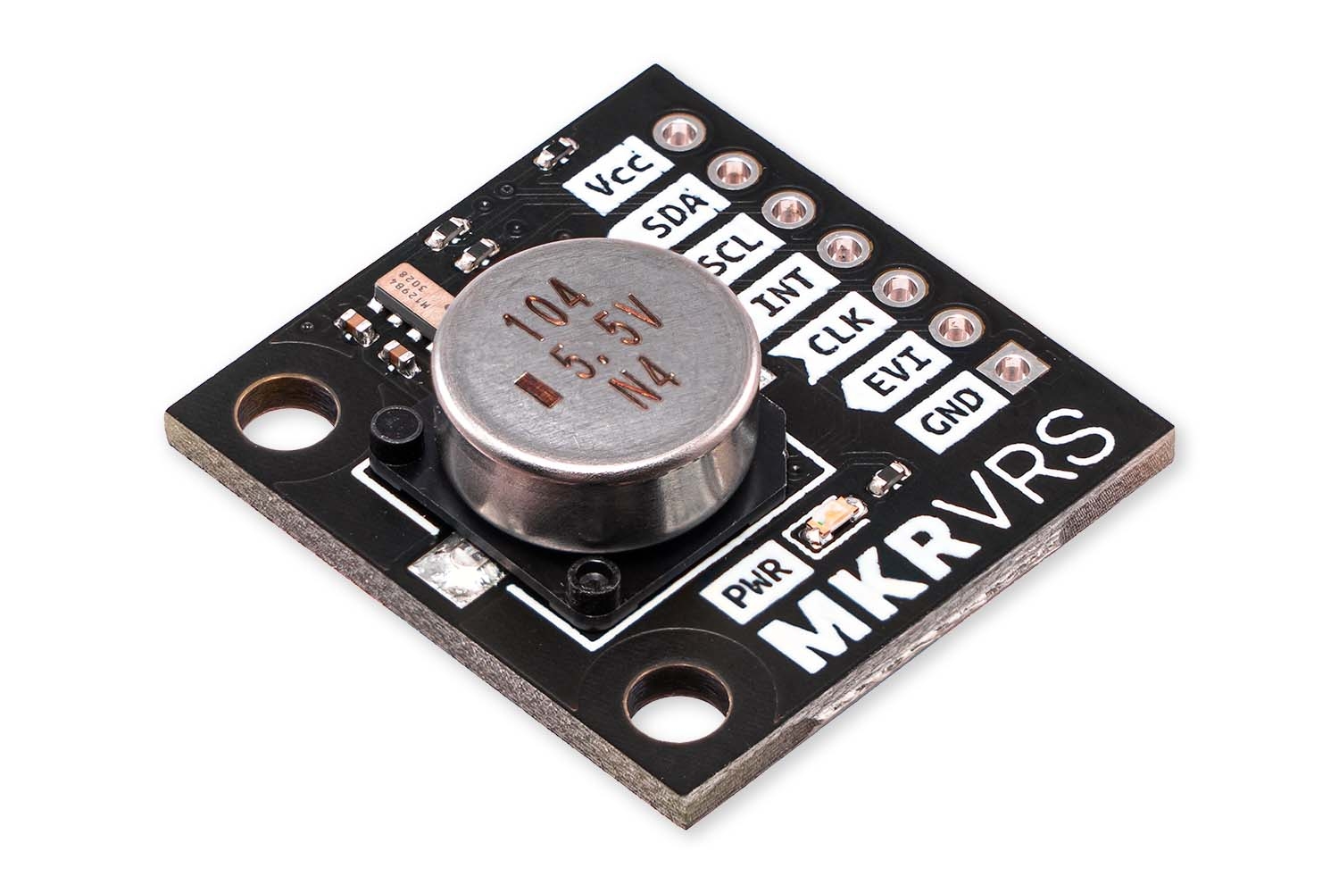
Accurate timekeeping, even during power outages.
Read more
2 Likes
Is it possible to trigger an event ie. set GPIO Pin high on the hour using a Makerverse Real Time Clock on pi pico.
1 Like
This doesn’t answer my question.
1 Like
Definitely is
1 Like
If you find that the responses are not quite what you expected it often helps to restate the question in a different form. Are you sure you meant exactly what you posted?
1 Like
Casting about for some ideas, one jumps out at me.
As far as I can tell, it is not possible to set the CLK pin to pulse every hour.
It is possible to set an internal alarm for one hour in the future, and have that trigger the interrupt pin. When the pin is triggered, a connected micro can wake up, perform the actions it needs to, then set the alarm for one hour in the future again. The alarm functionality is not implemented (yet!) in the Makerverse driver. Consider opening an issue on the repo if this is a feature you’re interested in.
Do you need precise hourly timing @Kenneth141839 ? Or is it a general, non-critical requirement?
You could build a frequency divider off the CLK pin, set up to pulse (nearly) every hour.
There is also the Makerverse Nano Power Timer which may be relevant to your interests.
4 Likes
Thanks for your reply. What I need is set aGPIO PIN on the hour I’ll have look at the nano power timer. Or use another RTC module.
1 Like
If you can read the time then you can detect when the hour changes and set the GPIO pin at that point. Presumably you want to unset it before the next hour, so your code could wait some time after setting it and do an unset.
If that is not possible for some reason you can indicate why not and someone might be able to suggest an alternative.
2 Likes
Thanks, I am a novice at writing python so I was looking for an example of code, after studying the List Function I have come up with the following code.
from machine import I2C, Pin, ADC
import time
from Makerverse_RV3028 import Makerverse_RV3028
i2c = I2C(0, sda = Pin(0), scl = Pin(1))
rtc = Makerverse_RV3028(i2c = i2c)
while True:
myTime =(rtc.getTime(time))
print(myTime)
hour = (myTime[0])
minute = (myTime[1])
second = (myTime[2])
print('Hour = ',hour)
print('Minute = ',minute)
print('second = ',second)
time.sleep(5)
This can get me started on my program.
2 Likes
Hi,
The RTC chip is great. Well featured.
The only thing missing from the module (for me) is a link/solder bridge choice to allow backup powering the RTC from another source, not restricting to just the supercap. This would make it more versatile and allow use in a wider range of circumstances. One more pin on the connector…
Maybe next build ![]()
3 Likes
Nice feature idea - a normally-closed solder jumper and a breakout pin for VCAP…
If we make a move on this project again we ought to add it.
As a quick and dirty hack, the capacitor can be desoldered relatively easily - and there is a test point on the underside of the board that connects to the capacitor positive terminal

3 Likes
![]() As of our most recent production run, this product features a 0.47 F capacitor (instead of the original 0.1 F)
As of our most recent production run, this product features a 0.47 F capacitor (instead of the original 0.1 F)
This upgrade is due to unavailability of the original capacitor.
Expect minimum charging time to increase by a factor of 5x, but also expect longer backup times as a result.
1 Like
I only seem to get just short of 2 hours backup for my RTC, it’s defaulting back to 0000. I’m still doing some testing on it (have purchased a display from you guys to help monitor). Is there any do’s and don’ts I need to be aware of for powering this unit? I currently have it powered from the 3.3v out of a pico pi and it’s charging okay, unless I need to allow more time for it to charge initially? It’s going on a gate controller in outback Qld so I need to make sure it’s bullet proof. Thanks ![]()
Hi @Brett272741
Sorry to hear you’re having some issues with that RTC, are you able to post a picture of your setup as well as any code that you’re using?
Hi Dan, thanks for reaching out. I’m pretty sure it’s power related, I set up some logging for it yesterday and it all worked fine through the night till I dropped the power for about an hour 40, then it went back to 0000. Here’s the code, I slightly modified the RV3028 code to just grab the time only in a 4 digit format. As mentioned it’s powered via the 3.3v out on the pico pi, I’m using a bread board power supply to power it. What voltage should i be seeing across the cap, currently it’s at 3.08v? Cheers

from machine import I2C, Pin #added I2C,
from utime import sleep_ms
sleep_ms(1000)#allow rtc to power up

from Makerverse_RV3028 import Makerverse_RV3028
from ssd1306 import SSD1306_I2C
#Define pins for Clock
i2c = I2C(0, sda = Pin(0), scl = Pin(1)) #added
rtc = Makerverse_RV3028(i2c = i2c) #added

# Define  OLED I2C pins and OLED display address (def freq 400000)
oled_i2c = I2C(1, sda=Pin(6), scl=Pin(7))
OLED_ADDR = 0x3c # =60 in hex
oled = SSD1306_I2C(128, 64, oled_i2c, addr=OLED_ADDR)

# Clear OLED display
oled.fill(0)

# Display 'start up'
oled.text("====start_up====", 5, 10)

# Push changes to the display
oled.show()
sleep_ms(1000)
#Define gate and led pins
gate_open = Pin(20, Pin.OUT)
gate_close = Pin(21, Pin.OUT)
gate_open.value(1)
gate_close.value(1)
led = Pin("LED", Pin.OUT)
led.value(1)
sleep_ms(500)
led.value(0)

while True:

    current_time = rtc.timestamp()#get_current_time()
    print(current_time)
    oled.fill(0)
    oled.text(current_time, 10, 10)
    # Push changes to the display
    oled.show()

    if current_time == "0500":
        gate_open.value(0)
        sleep_ms(500)
        gate_open.value(1)
    elif current_time == "0930":
        led.value(1)
        sleep_ms(1000)
        led.value(0)
    elif current_time == "0931":
        led.value(1)
        sleep_ms(1000)
        led.value(0)
    elif current_time == "0932":
        led.value(1)
        sleep_ms(1000)
        led.value(0)
    elif current_time == "1630":
        led.value(1)
        sleep_ms(1000)
        led.value(0)
    elif current_time == "1631":
        led.value(1)
        sleep_ms(1000)
        led.value(0)
    elif current_time == "1632":
        led.value(1)
        sleep_ms(1000)
        led.value(0)
    elif current_time == "2130":
        gate_close.value(0)
        sleep_ms(500)
        gate_close.value(1)


    for i in range(12): #repeat 12 times
        #uart1.write('at+test=rxlrpkt\n')
        #echo() # show debug data from LoRa-E5 module
        sleep_ms(5000)
Hey Brett,
Looking at the code, I can’t see anything that would be of concern. The voltage across the cap is actually a little higher than anticipated it should be 0.3V lower than the supply voltage.
If you try just using the RTC with the below code does it give you any different results?
import time
from Makerverse_RV3028 import Makerverse_RV3028

# Interval, in seconds, between data samples
logInterval = 1

i2c = I2C(0, sda = Pin(0), scl = Pin(1))
rtc = Makerverse_RV3028(i2c = i2c)

# ADC on Pin GP26
adc = ADC(0)

while True:
    x = adc.read_u16()
    print(rtc.timestamp(), x)
    # Opening with "a" for appending
    with open("datalog.csv", "a") as f:
        f.write(rtc.timestamp())
        f.write(',') # Comma separator
        f.write(str(x))
        f.write('\n') # New line
        f.flush() # Ensure data is written
        f.close() # Really ensure data is written

        # Wait for "logInterval" seconds
        timeNow = rtc.getUnixTime()
        while rtc.getUnixTime() - timeNow < logInterval:
            time.sleep_ms(100)
continueThanks Dan, it settles down to 3.05v across the cap when I drop the power, then after 2 hours of no power the RTC defaults to a time of 0000. I’ve now connected the RTC across the 3.3v buss coming straight from the power supply, will test that out and see if it holds up any longer after dropping power. I do have another RTC I can swap it out with but it’s bolted to a mailbox 1275k’s away ![]()

1 Like
Hi Dan, sorry I totally missed the 2nd part of your response. It ended up being my code, it didn’t like the 1 second sleep I’d left in there from the previous Lora config (that was necessary to allow the lora module to power up). Over the weekend I extended that timer which made things worse (wouldn’t last a few minutes without power) so I removed the sleep line and it tested well overnight, something I’ll keep in mind for future projects, thanks for your help on this ![]()
1 Like
Hi @Brett272741,
Thanks for the update, great detective work! Sounds like you’re narrowing it down.
Interesting that the sleep timing had that much of an impact on the RTC behavior, definitely one of those sneaky interactions that’s easy to overlook. Fingers crossed the new power routing from the 3.3V rail gives the backup cap a better shot at holding the time.
Also, love the commitment to debugging, but yeah, 1275km is a bit much for a hot swap ![]() Might need to train a carrier pigeon with a tiny screwdriver for that one.
Might need to train a carrier pigeon with a tiny screwdriver for that one.
Appreciate you sharing what worked (and what didn’t), really helpful for others facing similar quirks. Let us know how the next round of testing goes!
haha, don’t under estimate a good carrier pigeon ![]()
I moved the rtc power source back to 3.3v out and it’s working fine, a bit of spray paint on the lid to protect the circuitry for those 40+ degree summers and it’s good to deploy. Thanks to everyone at Core for your help and also for producing those great tutorial videos, they are really good for a guy like me who missed the whole coding thing at school and tech college.

1 Like