The lcds in both youtube clips are the size i’m looking for. I also want to add a blinking tap tempo to one of the lcds screens seen on the second youtube clip at time 4:21.
I have narrowed my lcds to the following
RGB backlight positive LCD 16x2 + extras - black on RGB SKU: ADA398 (use as small lcd? Still looks a little big for what i need, compared to youtube clips
)
3.2 TFT LCD With Touchscreen Breakout Board W/MicroSD Socket - ILI9341 as my main display.
ST7565 Positive LCD with RGB backlight for the smaller displays (use as small lcd? Still looks a little big for what i need, compared to youtube clips)
Adafruit 1.44 color tft lcd could replace the ST7565?
In Summary, I could use the main display 3.2 TFT LCD With Touchscreen Breakout Board W/MicroSD Socket - ILI9341 with the RGB backlight positive LCD 16x2 + extras - black on RGB SKU: ADA398.
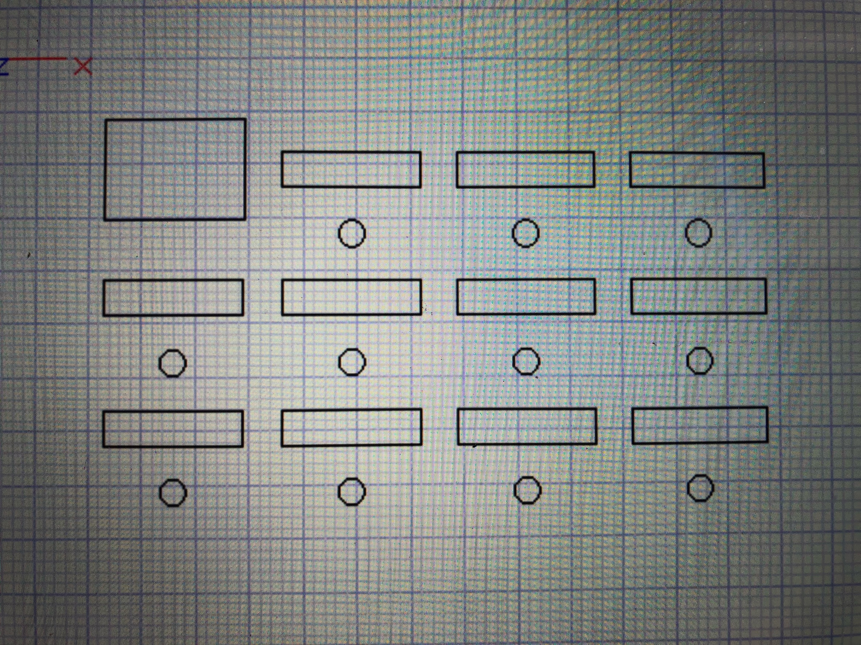
(I attached a quick layout of what it looks like on cad. Doesn’t look flash hot).
or
Use the 3.2 TFT LCD With Touchscreen Breakout Board W/MicroSD Socket - ILI9341 with the ST7565 Positive LCD with RGB
Not sure which way to go. I more so looking at the second youtube clip. That is the exact sizing I would like but can’t find anything to match?
Also I have to think of the most practical way to build this. Taking into consideration that the background of one of the lcd screens must blink at a temp eg 170bmp at max . The amt of wiring can be extensive with the graphic displays and the memory, hence why i’m thinking the Arduino Due and the 16x2 lcds.
Sounds like quite the build underway! I asked around, no one @Core has built something even remotely similar, so perhaps someone in our broader community can help out here in the forum?
Either way, please do share the build when done; we’d love to see it!
Hi Graham,
just wanted to ask a qq. What would be the best solution to hook up all of there lcds to a microcontroller. Do character LCD’s take up the same memory as the graphic displays. Hence whilist thinking to use the Arduino Due. I really think i’m going to run out of pins as alot of these lcds require at least 11 data pins each. Any suggestions would be great.
Perhaps you could use LCD’s with ready to use serial interfaces (such as I2C), or use a LCD backpack that provides a serial interface. There’s a few options either way here.
Another option is to use multiple HD47780 LCDs of any size variant, using the enable pin to control which is in use. Some customisations to the LCD libraries would be needed, no matter which option you went with.
It says " * Each R, G, & B LED has a 200 ohm resistor in series so you can power the backlight from 3V or 5VDC. R forward voltage is ~2.2V, G & B are ~3.4V" .
It says "You can try to connect Adafruit’s RGB 16x2 or 20x4 LCDs up but this backpack will not control the RGB backlight so you’ll have to use the backpack only for the 14 digital IO pins (pins #1-14) (will this work on the Due, do i need to put any risistors due to the pins voltages being 3.3)
and connect the backlight pins (#15-#18) directly to your microcontroller with 4 extra wires for color/PWM control as if they were just an RGB LED" (The backlight should be fine as right at the top of this post says it can run on 3v, but I could also plug it into the 5v pin of the Due?).
Also those pins (#15-#18), they would require 4 extra wires. Is pin 15 +'ve, pin 16 - red, pin 17 - green and pin 18 - blue? Just checking.
Also the backpack has it’s own potentiometer. Can I use this? Or do I need to run somehow a seperate one to control the backlight? Not sure how to do this?
Adafruit had these custom made to Adafruit’s specification so that you can use them in existing LCD projects and they’ll still work - just that only the red LED will be used. The extra two pins (17 and 18) are for the green and blue LEDs. The LCD has resistors on board already so that you can drive it with 5V logic and the current draw will be ~20mA per LED. There’s a single LED backlight for the entire display, the image above showing 3 colors at once is a composite!
I’m sure the Arduino Due spits out on it’s high current pin a max of 15ma, which may not be enough.
Maybe thinking of just using the Arduino Mega to run the one ST7565 LCD and 10x RGB 2x16 character displays with backpacks using the SPI communication protocol? I’m sure this would work, and i think I have enough memory with the mega. The ST7565 LCD uses 1Kb of ram. I’m not sure how much memory the RGB 2x16 characters displays use?