Mean Well Power Supply

Bought a Mean Well 5V 14A power supply from Jaycar.
First Mean Well I have ever bought and not too happy with it. Looking for someone who has had experience with these power supplies.

Set the output to 5.2V and measured the following voltage drops.
4.7 ohm 5.02V
2.2 ohm 4.89V
1.0 ohm 4.64V
0.5 ohm 4.49V

Is this normal ??
I didn’t expect it to drop so low so quickly, at 14A it would probably be down by 1V.

I have a 12V supply from a PC Desktop speaker unit, it drops by only 0.3V with a 2.2 ohm load. Looses regulation with a 1.0 ohm load which I would expect given its size.

Anyway, if this is how Mean Well supplies behave I will have to accept it, but I was hoping for better.

Regards
Jim

1 Like

Hi James
I have had dealings wth MeanWell power supplies for many years now.
I have found them to be pretty reliable and OK BUT I have never had occasion to check one as per data sheet.

The data sheet says load regulation is 1% over 0% to 100% rated load which @ 5V is 50mV. Your device is nothing like that.

It so happens I have one of these driving XMAS LEDs and 3 x 1Ω resistors mounted on heat sinks. If I get a chance I will check the performance of mine to-morrow and post results.
Cheers Bob

1 Like

You said your 12V PC speaker supply drops 0.3V with 2.2Ω (≈5.45A). That’s a much heavier unit (desktop supply, bigger transformer, probably linear regulation or high-quality switching), so voltage droop is smaller.

Mean Well LRS-350-5 is 5V/14A but very compact. It will droop more if you’re pushing it close to 70–80% of max current without excellent cooling.

1 Like

@Robert93820 Thanks for your reply.
On the Oscilloscope it meets this rating so I’m not worried about the regulation.
The problem is the voltage level drops lower than I thought it would.
Considering it will never be used up to its rated output, half a volt drop at 5A is probably ok.

MP3289_datasheetMain_77421.pdf (102.4 KB)

@ahsrab292840 Thanks for your reply.
The 12V supply is quite compact and is a switch mode supply. It powered an audio amplifier, and probably has been designed to keep the output voltage fairly stable. The audio amplifier died after many years, I think the heat sink paste dried up and the chip failed. Anyway intend to use the power supply as a 12V 5A supply. Happy with its output and regulation as per the Oscilloscope.

Think I will just have to accept the 5V will reduce under load, but regulation will still be good.

Cheers
Jim

1 Like

Hi James

A bit conflicting here
How come it is OK on an oscilloscope but not on what I assume to be a DMM.
I would have thought that regulation would mean that the voltage stays within 1% from 0A to full load, which with a DMM it isn’t but with an oscilloscope it apparently does.

You have my interest anyway so I will still check mine.

This surprises me as MeanWell have been a pretty good product. Confidence is also enhanced as the data sheet provides a figure I have not seen published for a lot of years now.
Namely MTBF. Quoted as being a bit over 681000 hours (78 years @ 24h/day). Fairly impressive.
Cheers Bob

2 Likes

Hi James
I checked my power supply and found it to be pretty good. Results below.

Open circuit 5.07V
Load 3Ω 5.07V 1.6A
Load 2Ω 5.07V 2.4A
Load 1Ω 5.07V 4.7A
Load 0.5V 5.06V 8.6A
Load 0.33Ω 5.06V 12.3A

As you can see the load regulation is excellent. The only reason for the discrepancy might be measurement technique. As you can see as the current increases the current/resistance does not compute exactly. This is because the connecting wire resistance plays a more significant role at the higher currents.

I measured the voltage RIGHT AT THE POWER SUPPLY TERMINALS which in all fairness is the only place it can have any significance. Is it the case you have not measured here
I say this as I have this output looped to a terminal block for easy connection to other devices and this wire is not that heavy. My measuring point was 150mm from the supply output. This resulted in about 120mV drop at 12.3A. While still significant still not as bad as your measurements.

I think the data sheet is quoted the voltage right at the supply output. The supplier has no way of knowing what the user is going to connect.

The solution. If the voltage drop is unacceptable use a heavier gauge wire. I believe this is the only way. If you start fiddling the output voltage it will be likely you could over compensate and supply over voltage to other connected devices.
Cheers Bob

1 Like

@Robert93820 Sorry I should have explained it better.
The DMM and Oscilloscope show similar voltage drops under load but the AC component is within the Ripple & Noise spec of 100mVp-p; sort of. (there are spikes at regular intervals under load which worry me)

When the load is high you can see the AC component increase on the oscilloscope and the spikes appear. From what I see on the scope I don’t think the Mean Well would make a good PC or Micro controller power supply.

The reason the output voltage falls is most likely the internal resistance of the power supply in series with the load.

Compared with the 12V supply the Mean Well 5V supply is not as good.

Regards
Jim

1 Like

Hi James

That is usually the reason.
My supply does not appear to have the same problem as yours. Well within the 1% quoted. 10mV from 0A to 12.3A or 3.33Ω. You measure 530mV from 0Ω to 0.5Ω. a vast difference.

The quoted load regulation is 1% from 0A to 14A. That is the output voltage should not vary by more that 1% over this load range. 1% of 5V is 50mV. My measurements only showed a drop of 10mV. Well within spec up to 12.3A anyway. I could not test above that.
So I could say you have a faulty unit or your measurement point is wrong. Should be measured RIGHT AT the output terminal.
I did not use an oscilloscope but will do so.
Cheers Bob

2 Likes

Good point. I did this and new results below.
No load 5.20V
4.7 ohm 5.15V
3.3 ohm 5.13V
2.2 ohm 5.11V
1.0 ohm 5.05V
0.5 ohm 5.00V

Much much better. So lesson learned; the problem is my wiring not the supply. BTW the oscilloscope AC is much better now too. The measurement point was a short length of wire attached to the terminals, removed what I had installed previously.
The measurement point for the 12V supply was at the wire coming out of the case.

Thanks for your help Bob, even at my old age I still have a lot to learn.

Cheers
Jim

EDIT: Also you have helped my understanding of the datasheet specs. Happy with this supply now.

3 Likes

Hi James
That is good.
The 200mV drop at 0.5Ω is a bit strange. It would be worth measuring at the 0.5Ω load again with the supply set to 5V. This is the design output but a small amount of adjustment is provided +/- 500mV with 5V at the centre of range. I wonder if it is possible the data sheet is guaranteed correct at only the designed output and that adjustment is only a bit of luxury and the specs might wander a bit when you deviate. My measurements were taken with the output very close to 5V.

As I said MeanWell have been a pretty much tried and proven product for many years to my knowledge. Their data sheet is also pretty impressive. Not many suppliers would provide information like MTBF and derating info. Most of the stuff available in this hobby environment provide almost nothing. That probably includes this so called “Official” RPi supply (plug pack I think). What is so special about it?? Except I think it is 5.2V. Has to be different I suppose.

If you really want a very stable voltage with varying load currents you should move the output voltage sensing out to the load. It then becomes a 4 wire system not unlike the 4 wire resistance measuring technique used for very small values.
I don’t think there are many readily available power supplies with this feature. They do exist though if you can afford it.
Cheers Bob

3 Likes

The following from the Raspberry Pi 5 documentation.

For users who wish to drive high-power peripherals like hard drives and SSDs, while retaining margin for peak workloads, a USB-PD-enabled power supply capable of supplying 5A at +5V (25W) should be used. If the Raspberry Pi 5 firmware detects a supported 5A-capable supply, it increases the USB current limit for peripherals to 1.6A, providing 5W of extra power for downstream USB devices, and 5W of extra onboard power budget.

Interestingly the USB-C PD spec has no 5V at 5A (see below).
The Pi 4 official plug pack is a Type-A.
The Pi 5 official plug pack does not fit any of the USB-C PD specs.

Labelling on the plug pack. I am pretty sure it only uses 5.1V.
5.1V 5A
9V 3A
12V 2.25A
15V 1.8A

If the PD power chip on Pi does NOT get the right message from the supply it complains in a pop up message, after the Pi has powered up. But you can switch it off in the configuration and it never appears, as I had to do when using POE to power the Pi. The Raspberry Pi corporation should have designed the Pi 5 to meet the USB-C spec, PD 3.0 PPS, but this would have required a major rework of the power system. (costly and time consuming) I love the Raspberry Pi just wish the Corporation would stick to standards.

Regards
Jim

2 Likes

Hi James
OK Thanks for that. I have learned something new also. I have not had any real dealings with RPi. Just general analog things that would pretty much apply to anyone.

Probably why I have not bothered. I just love people that make up their own “standards” then change them at will. Very little chance of any cross platform stuff that way and once started you have to be locked in for life. Personally I just like what is left of my life to be mine so i just don’t bother.

A bit like my Samsung phone. Only fast charges with a Samsung charger. But they supply that so I live with it.

Will have a look at that MeanWell supply with oscilloscope to morrow if I get a chance and report back.
Cheers Bob

3 Likes

Set to 5.0V, voltage drop was the same as 5.2V. So …
My measuring is no where near ideal and the connecting cables have way too much resistance at high current levels. So I set it up to measure directly at the terminals.

Set to 5.20V.
0.5 ohm load. 5.14V output. About 10A (not measured).
Close enough to the 1% listed in the specification.

Lesson for me is to take particular care when installing this and to use high quality high capacity wiring to the front panel. My current attempt leaves a lot to be desired.

Thanks for your help Bob, I have strong confidence in the Mean Well supply now and will proceed with what I planned. Bench 12V & 5V supply. The Mean Well was originally bought for another project which did not work out. Salvaging the 12V supply from an old PC speaker amplifier aligns with my “make things last as long as possible” attitude.

Cheers
Jim

2 Likes

Hi James

If everybody did this and left enough head room it would solve a lot of problems.
Worth remembering. EVERYTHING starts at the power source. If this is not up to the task any project is doomed to failure.

Good thinking. This is a proven product and I don’t think will cause much trouble.

As promised have had a look with an oscilloscope and have 3 interesting pics for you and anyone else interested.
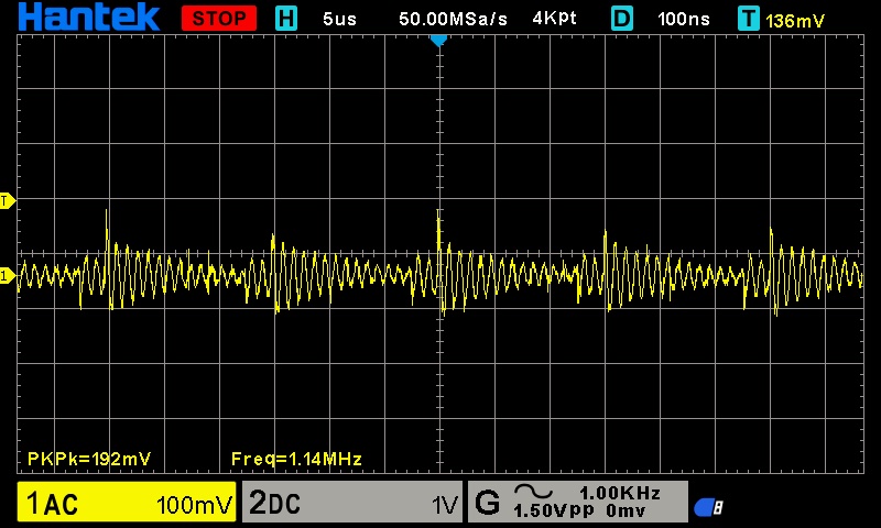
Pic 1. Output with 12.3A (highest I can test) load


As you mentioned this hardly makes spec but the next pic is interesting.

Pic 2. As above with the oscilloscope chassis (case) ground removed.


Having the ground in place effectively connects output negative to mains earth via the long route probe earth, mains lead to power supply then supply case. Quite a long ground path. I have a short mains extension with the earth wire disconnected for this express purpose. The wire is left hanging out of the connectors so it is obviously disconnected.
The supply negative is normally isolated from frame ground (confirmed by measurement) and is connect via a capacitor.
My measurements taken with oscilloscope ground clip connected to supply neg.

As you can see the "noise and ripple are now well below the 100mV spec.
The periodic spikes that you mention are still evident but the period has changed. But just about make it at 100mV.

Pic 3 is the result with the power supply off and unplugged. Output loaded for a few secs to discharge any output caps.


Interestingly there is still evidence of these spikes. This makes me believe that they may not be really there and are being introduced by measurement stray pick up from somewhere. The period seems to have change again.
I suppose anything could happen.
I hope this clears up the last of your doubts
I think this points out how easy it is to introduce spikes, ringing etc which is not really there. This sort of thing came up recently with long scope earth leads measuring I2C pulses.
removing the scope frame ground is a throwback to analog TV where having this ground connected to mains earth introduced all kinds of problems which were not really there. My oscilloscope frame is usually ungrounded but this is a new one and I just plugged it in.

I expect the absolute safety brigade will throw their hands in the air about this. Probably rightly so. You just have to get used to being careful. If you do things like looking at the voltage across a motor or similar you will probably have some sort of a disaster if you don’t remove the frame ground. Indeed in the past on TV instruments Tektronix provided this facility easily. You simple turned the 3 pin mains connector over and the ground disappeared.
Cheers Bob

Stupid me, can’t even read my own oscilloscope scale. Although I have an excuse, I have only had this one for a couple of days.

Big change: The horizontal scale is 5µSec/division. I was looking at the sample rate and reading 50mSec/div which was still wrong.
Puts a different light on things what???

1 Like

Thanks for your thoughts and pics Bob.

I connected the DMM leads direct to the terminals of the power supply and as the results proved much better, I considered the DMM leads. The probes on the original ones were very chunky so I replaced them with slim ones. Makes it easier to check connections close to each other without shorting anything. But may influence the readings because I think they are lower quality.

Your words on the probe ground connection and false spikes are interesting and I agree with what you have said.

Thanks again.
Jim

Hi James
Voltage measurements could be a bit more forgiving. The currents involved are minuscule. 500nA @ 5V. A few A current measurement will suffer most with poor leads. Although if the probe is very iffy nothing will save it.
Your test equipment, including any cables , has to be a lot better than the device under test (DUT). Otherwise any measurements are meaningless.
Cheers Bob

1 Like