This is a placeholder topic for “UPS Module with 5V and 3S LiPo Output” comments.
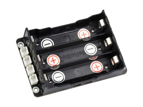
Uninterruptible Power Supply (UPS) Module, Supports charging And Power output at the same time, 3S & 5V 5A Output…
Read moreThis is a placeholder topic for “UPS Module with 5V and 3S LiPo Output” comments.
Uninterruptible Power Supply (UPS) Module, Supports charging And Power output at the same time, 3S & 5V 5A Output…
Read moreHi,
Happy Easter!
I am a little confused regarding an appropriate charger/power supply for this. Would I be able to use a Meanwell AD-155A? (I have one lying around).
Datasheet = https://www.meanwell-web.com/content/files/pdfs/productPdfs/MW/ADD-155/ADD-155-spec.pdf
I am leaning more towards no but thought I might clarify before obtaining new equipment. No point letting good electronics sit around getting wasted or going to e-waste after all :).
Thanks!
Regards,
Tony
Hi Tony
Probably not. The UPS linked requires a 12.6V supply to charge the 3S Lithium arrangement. This is clearly stated in the description. The rest of the charging smarts are built in.
The MeanWell supply is 13.8V to simulate a nominal 12V lead acid battery. I don’t know about this model but MeanWell usually provide a small adjustment of the output voltage. If you can turn it down to 12.6V it would probably be OK but if you can’t I would not use it.
Cheers Bob
Thanks.
I thought that might be the case. There is a adjustment dial but I am not sure how much it can adjust. I’ll have to check.
Oh well. I was just trying to avoid buying the suggested charger. As well as been rather expensive, it needs a 12V adapter itself. Making it pretty bulky too. Maybe I can find a simple standalone 12.6V charger through eBay or similar.
Thanks for your help again.
Regards,
Tony
Hi Tony
The specs say this is adjustable from 12V to 14.5V so you may be in luck. I have never needed to adjust any MeanWell supplies so I was not sure.
It needs to be 12.6V as that is the Max charging volts for 3S configuration.
Use a multimeter you can trust. Check CH1 output before you start, should be 13.8V. Historically MeanWell have been pretty accurate. Note CH2 will be different, 13.3V I think.
It is probable that the calibration status of your multimeter is unknown so if you can, measure with 3. The 2 closest ones will probably be more accurate.
Cheers Bob
Thanks Bob,
After doing a bit more reading, I might not risk it. The first channel provides 10A current and the second only provides 0.5A.
This pack apparently needs 2A I would be too worried that the 10A channel would blow something up :S.
At the moment, I have just been removing the batteries to recharge them in my Nitecore Li-Ion smart charger. It is a bit of a pain since the batteries sit in there quite tightly, but it works for now.
I am going to try and find a dedicated 12.6V wall adapter so that I can skip the charger recommendation (on the product page) and plug straight into the UPS.
Thank you so much for your help and advice. It is greatly appreciated for someone just starting out like me.
Regards,
Tony
P.S It is a shame that the UPS doesn’t have any voltage regulation on the charging side (from my understanding anyway). It would make it a lot easier if the DC input accepted a voltage range (12.6-14 or something). I would be too worried that my calibration with the meanwell supply is slightly off trying to get it perfectly to 12.6.
The charge controller chip has an input range of 2V to 24V, so the 12.6V is probably a minimum, not a maximum. A circuit diagram would confirm this - Waveshare might have one available.
The 10A available from the Meanwell is more than sufficient to power the module - it will draw a maximum of 2A. Current is not a concern - only the voltage.
/edit Waveshare can provide a schematic. The 12V supply feeds the MOSfets, the protection chip and the current monitor. The fuse is rated at 16V. The other devices are rated well above 16V (in the range 24V to 30V).
edit/
So you are saying that there is no issue with using 13V, or even 14V input? If that is the case it will make it much easier. I have several power supplies capable of providing that.
Why would waveshare have been so specific about using 12.6V? it seems strange to enforce such a restriction for no reason. As I do not fully understand the schematic I will have to take your word for it. Still in the process of teaching myself how to read them better (this one is too complex for me to understand yet. I’ll get there someday).
Thanks.
Regards,
Tony
I assume they are specifying it as a minimum - “Your power supply must be able to deliver at least 12.6 V at 2A”. The 0.6V is one diode drop, implying that there is a 12V minimum for the components. That’s based on an examination of the schematic, not any actual testing.
The schematic is actually fairly straightforward, as it is just a bunch of chips connected together, with a minimum of additional glue. To read it you need to have the datasheet for each of those chips available at the same time, and the data sheets for the chips can be quite dense. But to follow the power supply you don’t really need to know in any detail what the chips do (apart from the MOSFETs) just what their power supply specs are.
I have got a few of the data sheets. I started with the “INA219 high-side current shunt and powermonitor - I2C”. You are not wrong about them been dense. I am teaching myself all of this stuff with no prior knowledge (I am actually a pharmacist) and it looks like you have to be an engineer to really understand these datasheets. I am sure the schematic and data all looks straightforward to you but trust me, to someone like me, it really isn’t. To be perfectly honest I shouldn’t really need to understand it just to know what PSU I can use. Perhaps something got lost in translation (I don’t think the native language for the designers is English). Perhaps it is actually just me that is dense. Maybe even a bit of both ;).
I am going to go and re-read the wiki. Maybe I have misunderstood something along the way but I originally interpreted it to mean 12.6 specifically. If it can be slightly higher that is great news and far easier for me.
I really appreciate your help and expertise on this. Thanks again.
Kind regards,
Tony
Hi Jeff
The charging voltage for a 3.7V LiPo is 4.2V. three times 4.2V (3S) is 12.6V. That is the reason for exactly 12.6V
Cheers Bob
That would mean that the input voltage is the charge voltage and the charge controller is not doing anything more than switching the charge on or off according to the selected limit values. There is no actual voltage regulation happening.
Hi Jeff.
Yes that is correct. The controller is handling any diagnostic and “constant current” / “constant voltage” stages. Current bleed for cell balancing has to be handled somehow also.
Multipurpose chargers that handle a multitude of chemistries and cell counts (up to a limit) have a larger DC input and probably several regulators (or maybe a programmable system) for the variety of charging voltages required.
As this is a dedicated 3S charger I believe the required voltage will be the 12.6 charging voltage. There is another lithium chemistry that is nominal 3.2V (not 3.7V) and this really requires a lower charging voltage but sometimes 4.2V/cell is considered OK as long as this is absolute MAXIMUM. I have a small single cell charger that DOES differentiate between the 2 chemistries and reduces the charging voltage accordingly.
As is often the case the descriptive text says nothing about this and just indicates a 3S combination of lithium cells. I really think that for completeness the 3.7V cell should maybe be stipulated as use of a 3.2V cell would leave no headroom for a bit of error. Most hobbyists setting this voltage with a multimeter would have an instrument with varying specs and a completely unknown Calibration status if that ever existed at all. The error with a DMM can be substantial especially if the battery is depleted to the stage where it is barely working. This can be minimised by using a fresh battery for critical measurements but I digress, that is another subject completely.
Cheers Bob
Hi Tony
I just re-read this
You need to be a bit fair here. This is a copy of the data in the descriptive text.
| Output voltage | Batteries series voltage; 5V 5A; 3.3V 300mA |
|---|---|
| Control interface | I2C |
| Battery support | 3 x 18650 Li batteries (in series, NOT included) |
| Required Charger | 12.6V 2A |
| Dimensions | 60 × 93mm |
| Mounting hole size | 3.0mm |
This specifically states "Required Charger 12.6V 2A
That seems to be pretty clear.
Your query “can I use a 13.8V supply for this task” is probably fairly legitimate also.
I think the short answer to that is NO.
So to get back to your statement: No you don’t “really have to understand it”. Just use the power supply quoted by the designer if you are in any way confused. And believe me in this business it is not hard to get confused and even after many years of association it still happens so don’t feel too bad about it. Think of it as part of the learning curve which can be very steep at times.
Cheers Bob
Edited: Added decimal point to 12.6V
And you can get our latest projects and tips straight away by following us on:
![]()
![]()
![]()
![]()