Thanks Jeff! Super clear.
Worked a treat.
Im rocking 53 ma which is not much but might be sufficent. Testing will tell.
Thanks Jeff! Super clear.
Worked a treat.
Im rocking 53 ma which is not much but might be sufficent. Testing will tell.
Multimeters measure current using a very small resistance (0.1 or 0.01 ohm). They measure the voltage across it and calculate the current. Current must be measured in series with a load, always. At the same time you should check the voltage remains as you want it. Otherwise the load is too great.
If you just want to check how much current can be provided before the voltage drops too low. You can use a resistor divider as the load. Measure the voltage across one of the resistors and you can then calculate the current. Also you can easily check the total voltage to ensure it is not being loaded too much. Lowering the resistor values allows you to increase the current and find what can reliably be supplied.
I have a Digitech Multimeters similar to yours. It does not measure current as well as an older version I have that is analog with a digital readout.
Cheers
Jim
PS glad you got it working.
If the current required by the load is being supplied at the correct voltage, then it is sufficient - it is what the load requires. The supply might be capable of providing more current, but if the load doesn’t require it then it doesn’t matter. If the load draws more than the supply is capable of delivering then firstly the supply voltage will drop then the supply components will overheat and possibly fail.
Oh yes! I knew this! How silly of me. ![]()
A circuit just pulls the amperage it needs providing the amps are there.
I’ve demonstrated that this battery can output 3/4 of an amp, (admittedly in the stupidest way possible), so I know their is sufficient amps available to me.
Uh! I’m such a goose. Thanks @Jeff105671, your explanations are always so clear.
I think this is the sentence that made me interested in amperage available.
@James46717 are you saying that the 555 timer will prevent me from taking advantage of the full amp capacity of the 9v battery?
Hi Pix
Yes he is. The 555 timer is extremely useful but is limited in current capacity ( will not even drive most relays) and is used to operate other things with a higher input resistance such as Transistors and Mosfets. The actual size of the capacitors used is not going to improve the 555 capability but what James is saying if you go too small you will not realise the full capability of what is available. If you are talking about the small block type 9V battery such as in your DMM they don’t have much in the way of current capacity either.
So just what are we getting at here??? What is the overall picture??. If you are just trying to see if a charge pump works then you have done that. The result will be the initial 5V plus the 555 output (I don’t think this gets to full VCC) minus the diode drops at about 0.7V each, total about 1.4V.
Current measuring.
You are lucky you did not blow the meter internal fuse, (usually about 250mA on mA ranges)
Ill bet they did.
That is true for the 10A (A on that meter) range but this resistance is somewhat higher for mA and µA ranges. This causes what is known as “voltage burden” or the voltage drop across the meter itself. This will reduce the voltage applied to the DUT sometimes to the extent that it will malfunction or even work properly at the reduced voltage. An undesirable situation. For this reason series current measurements should be taken (where possible) on the 10A range where the very low resistance will cause minimal disruption or “non invasive” techniques, clamp meter or hall effect devices. Meters with enough digits will have a mA resolution on the 10A range and I have a very useful clamp meter which allows mA resolution with surprising accuracy.
If “voltage burden” cannot be avoided it can be overcome by monitoring the voltage at the DUT and increasing the supply to keep the DUT voltage correct. Seems a bit messy but is the only way out. If you are using a variable supply I think the voltage is monitored for regulation at the output AFTER the current sensing so this voltage burden is not a factor.
A basic precaution which is a very good habit to get into. If your meter is manual ranging like an analog (yes they still have uses) meter you would add “switched to the highest range”.
Cheers Bob
The datasheet suggests that the 555 timer grooves up to 200ma output.
Providing my future applications for a voltage multiplier don’t require more than that I should be chill.
The components included in this voltage multiplier circuit will also need a tiny amount of amperage, but the Absolute Maximum Rating allows ±225, and that is wiggle room I’m prepared to abuse! ![]()
Thanks everyone whole assisted me on this little adventure ![]()
I’m getting a little better every week. ![]()
Pix ![]()
Ensure the datasheet matches the 555 timer you have.
Some versions have limited current output but operate at much higher frequencies.
Most likely the one you are using will be ok.
I had not checked the datasheet for the maximum current output when I wrote my post, was relying on memory.
Hi Pix, James
I think you are going to try to use the 555 timer for something outside its design use. It is not meant to be a power source and at 100 or 200mA the output performance is not great as the voltage drop across the output components rises significantly.
The following is a bit from National semiconductor data sheet
Look at the numbers for 15V VCC @ 200mA. The output will swing from 2.5V to 12.5V which means that the 555 is soaking up 5V in the output transistors.
Pix that is why your charge pump did not get to 10V. 5 + 3.3 = 8.3, minus diode voltage drop (2 diodes) say 1.2V (could be 1.4V depending on current) = 7.1V as the output which is probably somewhere near what you got.
James is correct. There are quite a few variants of this very versatile chip these days and some are surface mount only. You need to check the suffix numbers.
Cheers Bob
Decided to see how this circuit works for real.
Theory only goes so far, nothing like seeing voltages and currents from a working circuit.
5V supply, 8.8V output. Two meters connected, voltage and current.
20K ohm load, 0.38mA current, output drops to 7.6V.
200 ohm load, 18mA current, output drops to 3.7V.
47 ohm load, 72mA current, output drops to 3.5V.
This confirms my theory, too great a load and the 555 charge pump no longer has an effect.
The output voltage is simply the supply minus the diode voltage drop. You can see the current path in the schematic I posted previously.
@Pixmusix try the 53mA load test again but use the meter to measure the output voltage.
Regards
Jim
Hi James
Supports my statement earlier that the charge pump is mainly used to jack up the switching gate or base voltage when NPN transistor or N channel mosfet is used in a high side switch or flywheel diode application in motor speed control. It is NOT normally used as a power supply.
Sometimes multiplier rectifier circuits (very similar to charge pump) are used in power supplies particularly where very high DC voltage is required but work slightly differently and supplied with AC voltage usually with a transformer. BUT the down side is load regulation. Can be pretty good with full wave reactivation, a bit worse with a voltage doubler and gets progressively worse as multiplier stages are added until it gets pretty unusable for any sort of current drain. Was sometimes used to generate the EHT voltages for Cathode Ray tubes as in old TV sets etc. This seemed to work OK as the load current is only a few µA or even pA.
Cheers Bob
Hi @James46717
I finally got around to running this test. I tried using it with 15v amplifier that requires about 300ma when at full gain.
You are quite right, the voltage multiplier output decreases when the total circuit requirements exceeds 60ma. For example, when I use it to power my 15v amplifier, it immediately drops to 10v (from 15v)
Totally awesome that you were able to predict that. ![]()
Earlier you wrote…
Just checking I understand…
You’re thinking I could try
Did I get that right?
Hi Pix
Substitute “Gate” for Base and essentially this might work. You will need a “P” channel Mosfet. The clock will be inverted but that won’t matter. The clock will also have to go far enough positive to switch OFF the Mosfet. I don’t know if the 555 will go high enough, depends on the threshold voltage of the Mosfet you want to use.
By the way, the 555 has to be powered by 9V for this to work.
If this 9V battery is one of those little block ones did you find out how long it will give you 750mA. Not too long I imagine. I would guess at about 15min or so.
Connect the 555 output (pin 3) to the gate via a resistor (1 or 2k)
Cheers Bob
@Pixmusix Having experimented with a real circuit I would change my statement.
Also I had in my head 50mA as the max. output of the 555 timer.
The datasheet clearly shows up to 200mA and only changes for higher frequency 555 timers.
I think there is more at issue than just the output current of the 555 timer.
The circuit design in my opinion is to provide a higher voltage but with little current output.
Maybe with the right components it would work better. In one of the pics it shows greencaps which are less leaky than the electrolytics I used.
A thought running through my head is to use a small transformer to step up the voltage. That way you are not relying on the charge / discharge cycle of capacitors. Going to see what I have in the parts bin and try it. The 555 timer output would connect to a transformer through a current limiting resistor.
Anyway, will try and see what I can come up with. There are probably other factors that will affect it too.
Regards
Jim
Hi James
Supports my earlier statement where this “charge pump” is used to increase the voltage to switch things like NPN devices in the high side switch for H bridges etc where the source/emitter voltage is already at full supply volts when switching is required.
It is NOT for a primary supply as Pix is trying to use it for.
A multiplier circuit (similar), transformer driven, was sometimes used where a high voltage very low current supply was needed and could tolerate the poor regulation. This I also stated earlier
I think this exercise is a learning adventure, if so it has been pretty successful even if limited to things you can’t do.
Getting back to fully isolated voltage converters now where a couple of transistors drive a transformer primary and the secondary is rectified in the conventional manner. I think that is the only way to get rid of the common ground without employing opto somehow. I have never looked into it. If I have needed an isolated ground I have always purchased one with this facility.
Interesting what you come up with if you can find enough bits.
Cheers Bob
Oh!
I’m not at all married to a 555 timer circuit.
When I googled “Voltage Doubler” These are the kind of circuits that came up.
I’ve had a lot of fun building it but it’s just a tool to get 15-20V
If you were in my situation and wanted to get 18V out of a 9V battery at the expense of some amperage, how would you approach it? What is the traditional way?
Hi Pix
We are all on a knowledge excursion here
The dead easy way would be to get a second 9V battery and connect them in series.
The other way could be to get one of the adjustable step up devices like the SKU Pololu-2890 or something like that ready made.
Another way would be to build uup an analog 240VAC to XXVDC power supply from scratch
If you are looking tp power something like your 15V amplifier I don’t think there is any easy way to do it from a lower voltage DC source to a higher voltage DC supply. The ready made devices convert the DC to a high speed switching signal and have a buck / boost arrangement. All done in a specialist IC. Not for us mortals.
Going the other way (high V to lower V) is much easier.
Cheers Bob
This is what I would use.
It ain’t cheap, but in my experience all pololu power supplies work very well and are very reliable.
They have fixed voltage ones but not at 18V. This variable one would get you the voltage you want at up to 2 Amps.
https://www.robotgear.com.au/Product.aspx/Details/4396-Pololu-Adjustable-9-30V-Step-Up-Step-Down-Voltage-Regulator-S18V20AHV
Haven’t had any success with what I mentioned before, don’t have the right parts.
But I tried the original circuit at 12V, produced 160mA dropping from 21V to 16V. Not too bad.
There isn’t one.
Regards
Jim
EDIT: Cheapest way is use 2 batteries in series, as @Robert93820 said. They would last longer too.
Hi All
I couldn’t think of any “traditional” way either. That is why the 3 alternatives above
Cheers Bob
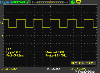
A pic says a 1000 words or so they say.
Testing from yesterday. !2V supply.
First pic shows 100mV per division. Was using a x100 probe and scope set to x1.
Output no load and 555 output.


Decided to measure at diode junction. You can see the shift in signal level which leads to the voltage doubling. 470 ohm load.
120 ohm load.

100 ohm load, no scope pic.
47 ohm load

Seeing the signal on the scope allows better understanding of what is going on.
Regards
Jim
EDIT: I also checked the output at pin 3 of the 555 timer, the higher the load the more distorted it becomes. At high loads the 555 output may fail after it has been running for a while. In my opinion you would not want the load to be greater than 100mA for a 12V supply and the output would be around 18V. If the output of the 555 was connected to a transistor the circuit might work better. Will try that.
Hi @James46717 and @Robert93820
Thanks for all your thoughts.
Ah no matter, I had a lot of fun with this project anyway. ![]()
I might have to stick to my 9V batteries in series solution.
Jim this was so cool to see! ![]()
The graphs show that decay in voltage as the circuit requirements increased really well.
Hope you had a bit of fun making it, thanks!!
Noted.
Thanks everyone for your contributions.
Hope you had as much fun researching this as I did.
Feels like though we were successful in the theory, the practical use cases of this circuit are too limited.
Seems like this will have to be my solution. ![]()
Pix ![]()
And you can get our latest projects and tips straight away by following us on:
![]()
![]()
![]()
![]()


