Hi Hasham
Do you not understand anything???
My suggestion was that maybe the output of this LINAC device was outside the frequency range of the photo diode. That is the photo diode might not detect the LINAC output. I just don’t know and am not about to go searching to find out.
You have not even answered my earlier question about what the exact conditions were when the oscilloscope pics were produced.
This last post is only a repeat of what you have already produced and bears no resemblance to your last post.
I think you are determined to keep going in circles and are not interested in doing things in a logical order so I think I am out of here
Good luck.
Cheers Bob
I am also a bit concerned about repercussions on the medical side of things.
1 Like
Dear All,
I need assistance in addressing the drifting DC voltage that I am currently observing in my two-stage transimpedance amplifier.
When I power the circuit using a dual power supply (±15 V), I notice that the output of the second stage amplifier, as observed on the oscilloscope, initially shows a DC offset of approximately –7.8 V. After about 15 minutes, the circuit stabilises, and the DC offset fluctuates only slightly.
The current gain of the two-stage TIA is 0.25 × 10¹¹ V/A.
Could you kindly advise on how I can control or eliminate this DC offset drift? Any guidance on stabilising the output more quickly or adjusting the design to minimise this behaviour would be greatly appreciated.
Thank you for your support.
Kind regards,
Hasham
1 Like
I mention that my background in electronics is limited, which is why I am somewhat uncertain about selecting the most appropriate IC. I have reviewed the specifications of OPA380, THS4601CD, and LMC6001. The first two devices offer relatively high bandwidth, but their input bias current is approximately 30 pA, whereas the LMC6001 has a much lower input bias current (~0.02 pA) but a limited bandwidth of 1.3 MHz.
I also tested the circuit by adding an RC filter at the output (0.1 µF capacitor and 10 kΩ resistor). This reduced the DC offset to zero, but the pulse signal still contained noticeable noise. All of these tests were performed using a function generator set to 360 Hz, pulse mode, with a 0.2% duty cycle.
I have also read that when the pulse width is very narrow, the effective gain is reduced, which may be contributing to the observed behavior.
Kind regards,
Hasham
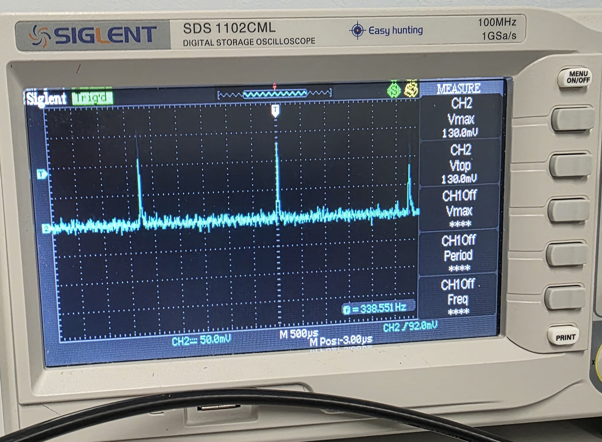
Could you please guide me on how to achieve consistency in the peak amplitudes of my signal? I am observing fluctuations in the amplitude of each pulse, even though I am providing a constant signal from the function generator (360 Hz pulse signal with a 0.2% duty cycle).
I’ve attached an image captured from the oscilloscope, where you can see that each pulse peak varies in amplitude.
For your reference, I recently changed the first-stage transimpedance amplifier IC from CA3140 to THS4601. and RC filter connected to output 0.1uF and 10 K ohm.
Any guidance on what might be causing these inconsistencies and how to stabilise the signal would be greatly appreciated.
Kind regards,
Hasham