I am in the midst of making a machine that scrunches A4 paper (for an art project).
I am at the stage of making a paper feeder, I am hoping similar to the one in this video, that can distribute paper into my scruncher mechanism. For context, I have little experience with electronics and engineering, so would appreciate some guidance if possible.
To make up the primary feeder (where the paper sits), I plan to use these flat belts, which are compatible (I think?) with these pinions. The pinions will be mounted onto d-shafts, driven by a stepper motor (already purchased).
I assume the D-shafts have to be put into bearings so they rotate freely? Is there an alternative to the d-shaft and/or pinions linked?
For the second feeder (the bed where the paper is pushed onto sheet by sheet), I plan to use these round belts, which will be mounted on a 3D printed pinion on a shaft with bearings. These belts will direct the sheet into my scruncher. Again, some recommendations here would be great.
I also require some sort of sensor, so I only dispense 1 sheet at a time. I assume something like this should do the trick?
Also to note, is that n the video the paper that is not fed (in the cache) is held back with a rubber pipe (see seconds 42-44). Looking other ways to do this? My current idea is 3D-printed block beveled at the bottom, as to gently let out one sheet at a time.
I think you’re reaching out to see if you’re idea has merit.
Is that right?
I certainly all seems promising hey?
Good ideas, I think you’re idea of a bevilled block will help, might need some felt glued on the bottom for more friction but that’s the kind of thing you can iterate on in the testing phase.
To comment further, I would love to see a full drawing of the whole setup as you see it, including any circuits, movers, UI, etc. Seeing it all in one place will help me visualize what you’re visualizing and maybe spot a ɠɾҽαƚ ʂαԃ before it happens.
CE may be able to comment more on what products are compatible with what.
I think you will need some kind of side guardrails to guide/force the paper through the block filter.
That filter will need a pretty smooth 3d printed surface to prevent the paper from catching on any imperfections. I still recommend some kind of tape or felt.
Look on the whole seems promising.
Obviously I have never tried anything just like it, so be prepared to experiment.
I maintain that if I had to do this I would be peering over my shoulder at all those pretty little commercially available printers. Paper feeding trays and motors lounging around and taunting me with a ready-set-go, tested, solution. Can you remind me why that wasn’t viable for your needs?
Just brain storming here, so these thoughts may already be covered.
At a high level I see the following.
the ability to have a stack of paper that can be feed one sheet at a time… this seems to be what your looking at above and in the video….
the ability for that one sheet to be “processed” (scrunched) one sheet at a time.
So, in my mind there also needs to be some “sync” start/stop of the paper feed while the scrunched does its thing.
i.e. feed on sheet into the scrunched, stop the feeder, start the scruncher, remove scrunched paper and repeat…..
Note: this could also be handled via some correct timing.
e.g. feed sends paper into a “holding tray” while the previous sheet is processed. when the processing is complete the holding tray “drops” the next sheet into the scruncher and the next plain sheet is feed.
My key point, is that you may not be able to just keep feeding paper as the paper processor could be busy and not ready to accept it.
Hi @Pixmusix , thanks for the suggestions! I will definitely be using guide rails. The whole thing will be inside an acrylic cage essentially, with 3D printed supports where needed.
I agree, I think that the bevelled blocker needs to be finely tuned. Felt is a great idea. I will experiment with different shapes and materials.
I am hesitant to use existing machinery for artistic purposes. Aesthetics and also to keep everything in the same ‘ecosystem’. I also see it is a good challenge / way to learn by doing it all myself.
But yes, it does make things more difficult than it needs to be!
I am thinking of using an infrared sensor to indicate when parts of the machine need to stop and start (i.e. stop driving the stepper motors). I have never used one of these sensors before so wish me luck. I’m sure I will need to spend a lot of time adjusting the timings.
My biggest problem right now is how to get the paper from the feeder into the half cylinders…
Perhaps using a servo with a rubber wheel in either end of the cylinders to roll the paper up and around?
That’s really understandable.
I’d like to clarify that when I’m suggesting a printer, I’m suggesting you strip it for parts. Pinch the wheel rollers, pinch the rubber guides. Look at the motor and measure it’s speed because I bet that turns out to be important. See what you can learn from it, what did the pros learn yesterday that I can skip today. Then if any of the parts are useful, grab a screw driver, pull it out, and put it into your machine.
With that said, there is a “DIY & Vibed It” aethetic that is really potent in our era of 'hyper-manufactured/on-demand’ so you’re artistic sensibilities are absolutely worth sitting in if you’ve got that gut feeling.
It could be worth using two sensors: one positioned at the feeder exit and another at the scruncher entry. You’ll also want to experiment with the paper’s distance from each sensor to find the optimal placement and minimise false positives.
As Pixmusix mentioned, it can still be worth raiding old printers for parts. Many of us end up with a stash of “useful” bits this way; it’s hard to resist taking something apart and hanging onto the good pieces for future projects!
Just be careful not to design yourself into a corner, leave room to tweak things wherever you can. The big three to watch are feed angle, roller pressure, and stopper tension, as small adjustments here can make all the difference in reliability.
Im trying to picture how it works…. so the paper (is rolled) and “placed” in the cylinder, then a piston compresses the cylinder of paper into a “ball".
The follow are two thoughts, the first one is easier to deal with the forces, but more complex to impliment as it adds another “transfer process”. The 2nd is simplier, bit relies more on the resistance being low enough that it works, may need to apply a bit more force to feed the paper into the cylinder.
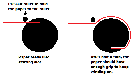
What Im kinda picturing is a smaller tube with a slot. one sheet of paper is fed into the slot, then as the paper is still getting pushed out from the stack, the roller turns, effectively wrapping the paper around the tube. That then is “feed” in to the scruncher and un-wound such that the tube can be removed. the scruncher cylinder would hold it in place for its action.
e.g. side view
I was wondering if an offset slot would be enough, such that you could just apply enough pushing force to roll it inside the scrunch cylinder, but I think that will depend on how tight it gets.
Hi @Michael99645 , this is really cool. I like your suggestion of the half cylinders rotating while the paper is still being fed, to trap and wrap it into a tube. In my plans so far, I don’t plan on making the cylinders rotate, but I definitely could do this…
In your second option, I’m thinking the feeder will not have adequate power to force the paper all the way into the cylinder (it might, but I need to test this).
So I went away and implement some of your suggestions. Here is my update.
I managed to make a scruncher prototype consisting of two open cylinders. In my third iteration (shown in the videos below), one cylinder is slightly larger than the other, which allows one to push into the other, compacting the loaded sheet.
See video of scrunchinghere. Apologies in advance for the crude set up! This is very much a prototype. Also, I’m still figuring out how to efficiently work my stepper motor, so apologies for the grating noise!
Some important things I have discovered in my prototyping.
Diameter: The cylinders have to have a diameter fairly similar to what is shown (i.e. 8-10cm). Much smaller, and the paper is too robust (as a tube) to scrunch. I found that paper in an incomplete U-shape, rather than an entire O-shape is much weaker and easier to collapse. if the U-shape is much larger, the paper will not scrunch sufficiently into a ball for my liking.
Length: The cylinders also must have length fairly similar to what is shown (roughly 8cm wide). Much smaller and, when inserted, the paper will not conform to the cylinders, but instead funnel out the gap between the pipes.
While these discoveries have brought me some success and hope, there are still problems. My biggest hurdle is that the paper, post-scrunch, is jammed within the confines of one cylinder.
If the paper was jammed within the moving cylinder, I thought it could be unjammed upon retraction. i.e. the right cylinder could retract past it’s origin point and into some fingers which would dislodge paper from behind. However, it seems the paper wants to get stuck in the left (static) cylinder.
Any ideas of how to get the paper out post-scrunch?
What if the paper was compressed within a closed cylinder, where one side moves inwards? Like this can crushing machine. This way 1. the paper will definitely conform to the shape of the cylinder and 2. the paper can be compressd almost entirely to the opposite wall.
While this may be an extremely effective scrunch, the big drawback is releasing the resulting scrunch. Unlike an aluminium it will not fall away neatly.
I’m wondering if the pipe and/or compressor disc could be shaped in a way to simply push the paper out a hole?? Or if the left wall could open and the paper be extruded out upon meeting a distance threshold?
The keywords that will make this work is “constant angle”. As long as the friction and normal’s don’t change objects, like paper for instance, should happily travel down “through” the helix. It will resist at first ofcourse but that’s what you want because it will give you some of that sweet sweet scrunching.
This is how a drill makes a hole, the wood shaving travel up the helix and out of the way, revealing fresh wood.