My current project is to use a Pi Zero W & Phat DAC to add bluetooth audio to my car stereo. The bluetooth and audio parts works flawlessly. The difficult part is how to power the system so that the Pi has time to switch off gracefully. I have found many threads about adding a UPS to enable shutdown but I find these all far too bulky and would like to explore a different solution.
The car stereo has 2 power options 12V permanent, 12V switched. I would like to power the Pi via the permanent 12V and use the switching supply to send on/off signals to the Pi.
The Pi can be powered on (after shutdown) by shorting pins 5 & 6
The Pi can be powered off via a script watching a GPIO pin.
The logic is simple:
If ~12V -> connect pins & GPIO high
else disconnect pins & GPIO low
My first question:
Is this a bad idea?
If not:
Can someone help me with the circuitry to make this work?
I have had some thoughts but I am not very good with circuits. A mosfet, a zenner diode and some resistors should do the job I think?
Thanks,
David
NB I have a 5V stepdown regulator connecting the 12V to the Pi.
That sounds like a good idea to me, The way I would do it would be to step the ignition Power from 12V down to a bit below 3.3V (probably about 2V) and use the zener diode to protect the Pi pins from over voltage.
I know this is an old post, but in case it helps anyone else, I found an article here
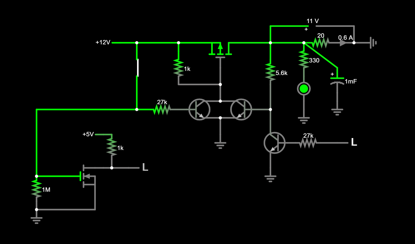
which has a very simple circuit that I am going to use for my car RPi project. When the ignition switch is on, the RPi will power up. When the ignition switch goes off, the RPi receives a signal and will gracefully shutdown. When shutdown is complete, the RPi signals the circuit which then disconnects power from the RPi. This uses dtoverlay in the RPi config file and two GPIO pins. You can also monitor the shutdown pin in your Python code (instead of using dtoverlay) and issue the shutdown from Python.
I’ve built this on breadboard and tested it - works well. Hopefully it works in the real world too!
No need for a UPS as the circuit is permanently powered by the car battery, but the RPi is fully disconnected so it draws no current when ignition is off.
Well in the real world the above circuit does not quite work .
The basic circuit works fine when not connected to the RPi and triggering the power off pin manually by pulling it high.
But when you have it connected to the RPi, the RPi immediately re-boots after shutdown.
This will probably be hard to follow, but here goes:
The problem appears to be that when the RPi shutdown pin goes high to signal it is safely shutdown, the power is cut only momentarily - long enough for the RPI shutdown pin to go back to low, but because the buck converter has capacitance, the power comes back immediately and the RPi reboots. The shutdown pin needs to be held high for a second or so to ensure the circuit switches off.
I’ve been able to simulate this using CircuitJS (http://www.falstad.com) but so far I don’t have a fix . Anyone got any ideas?
Hi Steven
I haven’t really been following this but I did notice a couple of things in your posts.
Just how does the RPi send a signal when it has shut down.
Why wouldn’t the RPi pin go low when the power is removed.
I haven’t had a play with RPi and try to stay away as long as possible. But I can’t see how you can expect a pin to stay high when the power is removed. Magic maybe or is there a phantom battery that nobody knows about.
Just an observation.
Cheers Bob
Hi Steven
Just had a look at your linked circuit.
As I see it I think the sequence of events should be as follows.
When ignition is turned on Q2 is ON which turns Q1 ON applying power to USB_PWR. Q5 is ON pulling Shutdown LOW. A LOW signal from RPi Poweroff pin turns Q4 OFF and Q3 ON thus latching Q1 ON.
Ignition OFF. Q2 is OFF. (Note Q2 base could do with a pull down resistor here as if left floating could cause problems) Qi is still ON due to RPi LOW on Poweroff pin holding Q4 OFFand Q3 ON. Q5 is off (Via R5 Pulldown) and a HIGH signal appears at Shutdown pin. When RPi shuts down Poweroff should go HIGH turning Q4 ON and Q3 OFF thus turning Q1 OFF and removing power from USB_PWR.
You have a bit of a chicken and egg situation here where when power is removed the Poweroff pin cannot remain HIGH and must go LOW. This will leave the base of Q3 floating and it is highly likely Q3 will switch on again. If this happens Q1 will power up USB_PWR again and everything will start up again until Poweroff sees another HIGH signalYou might try a pull down resistor on Q3 base to make sure Q3 remains OFF until power is restored via Q1 turning ON at the next ignition switch on. You may have to experiment with values.
Cheers Bob
Many thanks for taking the time to look at this Bob, I appreciate your comments, and the explanation of the circuit logic - its not my design so your description is very helpful for me. PS - confirm that where you wrote Qi in the Ignition OFF paragraph, you meant Q3?
I have found that the circuit behaves erratically eg when IGN is off and 12V is first connected it sometimes powers up USB_PWR immediately whereas it should not do that until IGN is on. I thought it might be the base of Q4 needed a pull down but I don’t think that worked when I tried it. I will try your suggestion of a pull down on Q2/Q3 base…
I have noticed that if I leave the Poweroff pin disconnected from the RPi and I control its state “manually” by connecting it to 12V when I want to remove power from USB_PWR, if I do it momentarily, then the circuit interrupts power but it comes back right away. I have to hold the pin high for about a second before the circuit powers down.
Intuitively I thought that might be caused by capacitance in the USB buck converter, keeping its output voltage high for a little while. RPi would have no power for an instant, so its Poweroff pin would go low and immediately power would come back and the RPi reboots, hence my comment about a latch triggered by Poweroff to guarantee it stays low, and unlatched when IGN is on again. However I tried an LM7805 regulator instead of the buck converter, thinking it would power off instantly, but it makes no difference.
No, Q1 and Q3 are both on until a HIGH is received at Poweroff which switches Q4 ON and Q3 and thus Q1 OFF. Q3 is the latch keeping Q1 and USB_PWR ON until the RPi is ready to have power removed.
You are probably right. That could be happening and that would do it. You haven’t by any chance put an extra capacitor on the buck converter input have you? If so, remove it as it will do nothing for fast spikes (due to internal inductance in electrolytic caps).
You could probably fix this by inserting a schottky diode in series between the junction of Q1 drain / R3 and USB_PWR to prevent voltage back feed. I suggest schottky as they are fast and have a lower voltage drop but as you are converting down anyway this voltage drop would be of no concern. You never know it is a simple fix and just might work.
Cheers Bob
PS. Diode connected Cathode to “USB_PWR”. Pull down resistors mentioned earlier still would not be a bad idea to stop the bases floating.
Bob, you are a legend!
The Schottky did the trick…
Thanks a million for solving this problem
I did not put any extra caps in the buck converter. It has a 220 on the input and a 100 on the output side. Could you elaborate a bit more on why there is voltage feed back?
This is the converter:
I’ll update the circuit diagram and post it here later…
Thanks again!
The 220µF will be charged to about 12V until Q4 gets a signal to switch off power. When Q4 switches ON Q3 and thus Q1 will turn OFF. The charge on the 220µF cap should discharge through Q4 via R3. Now this will take a finite time. In fact it will take 1.23Sec (1 time constant)for the voltage to fall 63% that is to reach 37% of 12V which is 4.4V. 5 time constants is regarded to be the time to fully (theoretically the cap can never “fully” discharge) discharge and this is something like 6 Sec. Keep in mind that while the base voltage is about 0.7V above ground transistor Q3 will be ON or partly so. Also there is probably 0.1V or so drop across Q3 while it is ON.
The diode you inserted blocks this voltage from switching Q3 back on. It also prevents the cap discharge via this route but this does not really matter. It allows Q3 to unlatch Q1 and stay unlatched until the next ignition cycle.
Cheers Bob
PS. I omitted to mention that in practise this timing will be a bit faster as there will be other discharge paths for this 220µF cap within the Buck converter which would be effectively in parallel with the R3/Q4 combination.
Hi Liam, Steven
Thank you for the thank you. Doesn’t happen often.
Unfortunately on the Forum there seem to be far too many unresolved cases. That is no published resolution where the person doing the helping is left with no idea whether his or her solutions have been successful or not. In these cases nobody gains any knowledge, The helper or the interested reader.
Personally these days I look closely before I reply. There have been cases where a student is trying to get everybody to do all the work for them so they might get an assignment in on time. It has been actually stated that there is a time limit on the help due to this. This is not learning. Half of the lesson is knowing where to do your research. So the student gets his assignment in without learning anything, gets his marks then eventually graduates then gets foisted on the public as being qualified for something he actually knows very little about. I know this is an exaggeration but you might get the general idea. As soon as I get a sniff of this happening I back off.
The other no no is when a problem emerges as being a commercial project. This is dangerous ground if you offer advice which goes belly up and you don’t have professional indemnity insurance (which the hobbyist is very unlikely to have) and all sorts of nasties can come out of the closet. I have come across a couple of these and drop them like a hot potato.
All things considered the Forum is pretty good though but it would still be a help if results were published so one might know if the info passed on has been useful in getting a result.
Cheers Bob
I’m really glad that I found this thread. I am currently facing the same issue as Steven but adding a schottky or the pull down resistors sadly didn’t do the trick for me.
I was hoping that Steven might be able to share an updated schematic? I’m not really good with electronics, it’s just a little side hobby so I’d really appreciate your help.
I cut the trace between the junction and usb power where I inserted the schottky and as pull down resistor I used 1M Ohm.
Sometimes the circuit works on the first try but fails afterwards and the Raspi just reboots.
I don’t have anything to offer to this thread except many thanks for posting your solution! As Robert says a lot of people don’t post their solutions, and hence the knowledge is lost.
The later part about commercial projects is a worry. Might have to add a clause to the end of my posts disclaiming any responsibility for something I have no control over. ie What they do with any advice I have provided.