I recently purchased a PiicoDev_BME280 sensor for use on my Raspberry Pi Pico. I have used this before successfully, this was just a replacement for the last sensor that I managed to get rained on and ceased working! I have connected as per previously but I2C cannot detect the sensor. I have tried address x077 and x076 to no avail. I am using a modified adafruit bme280 driver on micropython with thonny on pins 4,5 as before which I had no problem with. I have even downloaded the PiicoDev_BME280 driver with the PiicoDev_unified driver and connected sensor to pins 8,9. Still cannot detect sensor. I have tried both options on a Pico2W and Pico original to no avail. I am 99% sure sensor is faulty.
1 Like
Hey there, @Anthony181864, and welcome to the forum, glad to have you here.
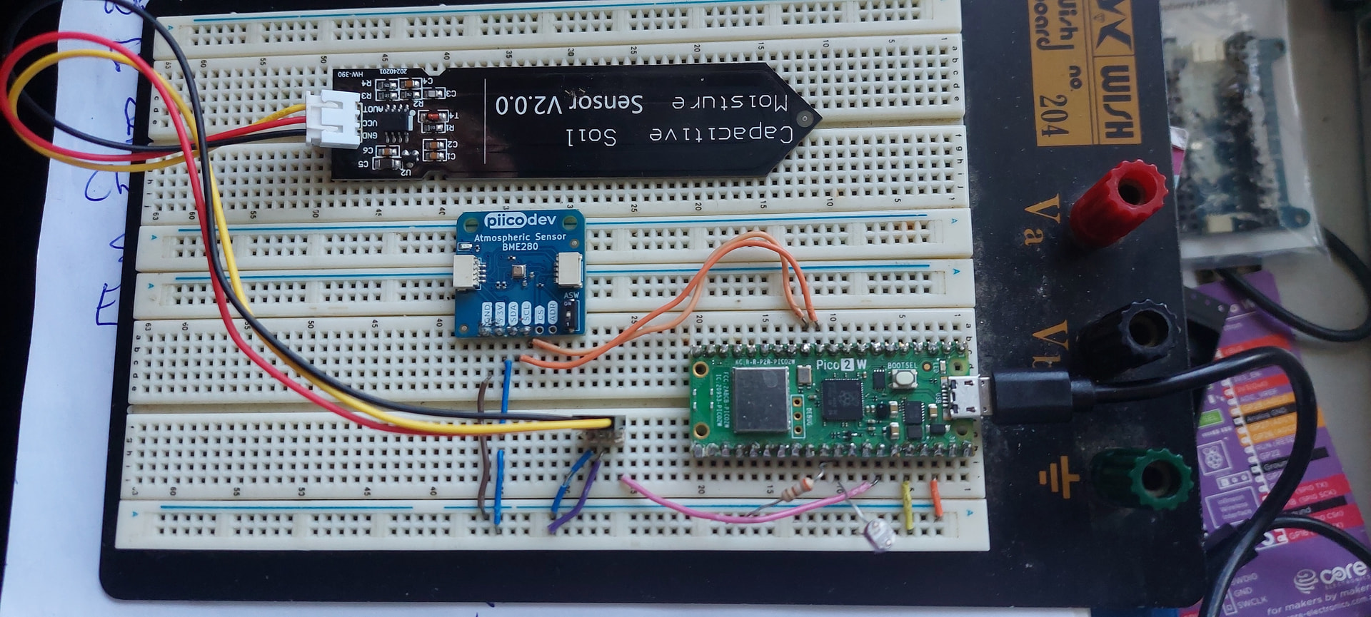
Based on everything you have described so far it definitely sounds like there’s something funky with the sensor. Would you be able to upload your code and a picture of your setup so we can try and see if something’s going wrong?
Hi. I have attached the 2 different drivers and programs with corresponding setups. I used the bme280_test with bme280.py driver (pins 4,5) with i2c error:Traceback (most recent call last):File “”, line 10, in File “bme280.py”, line 98, in __init__OSError: [Errno 5] EIO. I then tried PiicoDev drivers and program (pins 8,9) with i2c error: PiicoDev could not communicate with module at address 0x77, check wiringTraceback (most recent call last):File “”, line 9, in File “/lib/PiicoDev_BME280.py”, line 32, in __init__File “/lib/PiicoDev_BME280.py”, line 29, in __init__File “/lib/PiicoDev_BME280.py”, line 64, in _read16OSError: [Errno 5] EIO. I actually have an E100 Micromite computer which i have used with bme280 sensor before. I connected this up and ran program. It read the bme280 sensor perfectly? I have also run an i2c scanner program on the pico2W and it detected it fine at address 0x77. I am at a loss!
(Attachment bme280_test.py is missing)
(Attachment bme280.py is missing)
(Attachment PiicoDev_BME280.py is missing)
(Attachment PiicoDev_Unified.py is missing)
(Attachment piicodevbme280test.py is missing)
1 Like
Thanks for that, @Anthony181864,
First thing to note is that the Ground connection on the Atmospheric Sensor is looking a loose there and it could cause periodic disconnections.
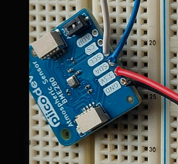
Secondly, could you please show us a photo of the underside of the Atmospheric Sensor so that we can double check the soldering for any poor connections.
Thirdly, none of your code has made its way onto the forum. Could you include just your main program into your next forum post between two pairs of ``` ``` . The backstrikes will format it so it’s easy to read.
sorry about first email, very slack on my behalf. I have attached new photos of bme280 sensor with pins soldered and checked all connections to pico are OK. I have attached bme280 driver and test program as a txt file as well as the PiicoDev_BME280 driver and test program. I will also attach the associated thonny error messages for each. As i said before i can get the bme280 sensor working on a different microcomputer so thinking my drivers are not correct?
(Attachment bme280_test.txt is missing)
(Attachment bme280_test errors.txt is missing)
(Attachment bme280.txt is missing)
(Attachment PiicoDev_BME280.txt is missing)
(Attachment PiicoDev_test errors.txt is missing)
(Attachment PiicoDev_Unified.txt is missing)
(Attachment piicodevbme280test.txt is missing)

1 Like
Hey there, Anthony,
Thanks for that.
I think there might be a misunderstanding re: emails. You might be seeing them as emails and replying to them, but I’m seeing them on Maker forum which unfortunately doesn’t allow for attachments beyond images.
Could you please reply with just the test_errors.txt and you’re main code between ``` ``` so I can look over it. Otherwise, all I can see is:

‘‘‘
PiicoDev_BME280testerrors.pdf (28.3 KB)
PiicoDev_BME280test.pdf (32.9 KB)
PiicoDev_Unified.pdf (75.6 KB)
PiicoDev_BME280py.pdf (58.2 KB)
bme280_testerrors.pdf (24.3 KB)
bme280_test.pdf (35.2 KB)
bme280py.pdf (97.4 KB)
1 Like
Hi Jane, Anthony
I notice that has not happened.
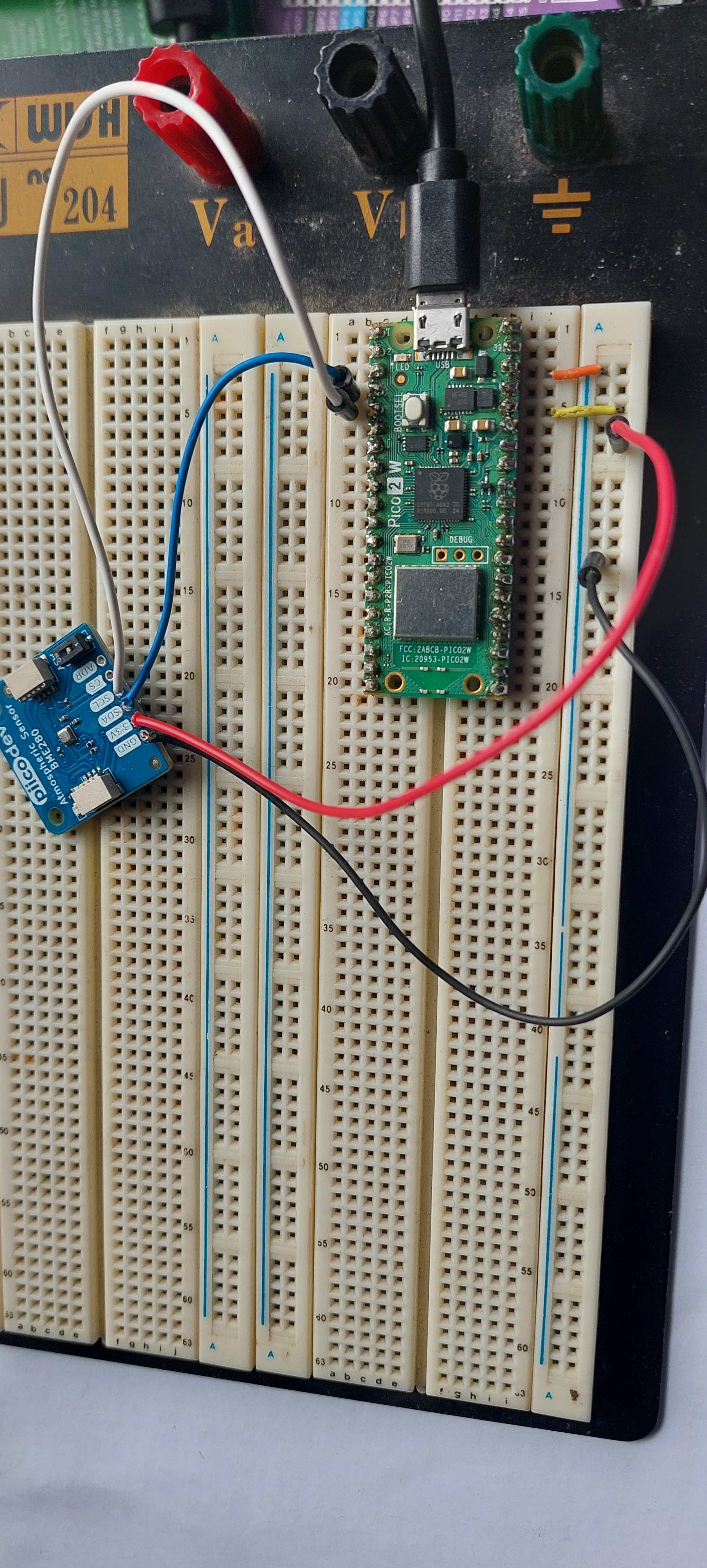
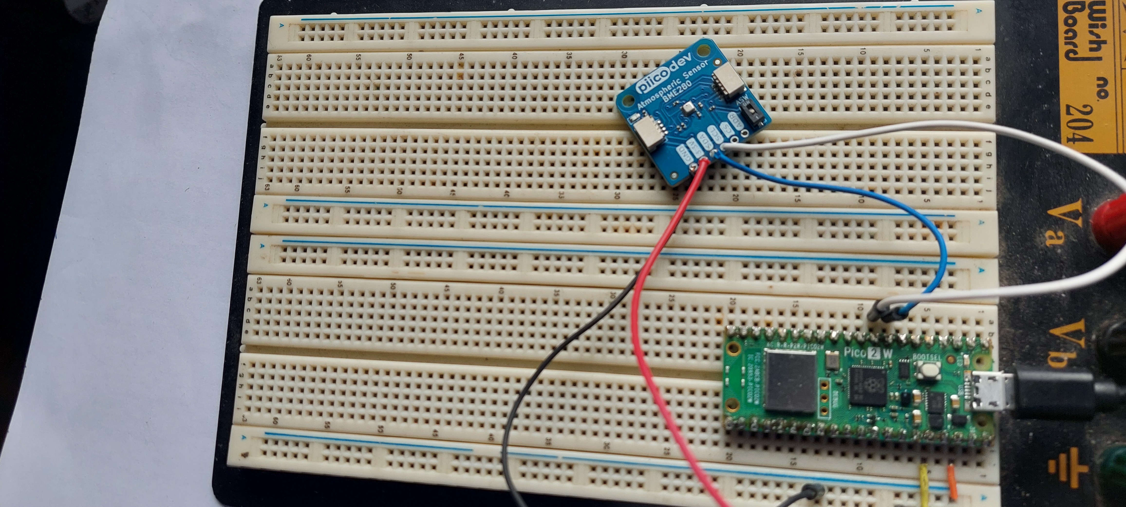
The latest pic looks like a header strip has been fitted. Unfortunately that part of the pic is so far out of focus it is very difficult to see anything pertaining to solder joints. And the parallax error is so great it is difficult to tell with any certainty which strip on the breadboard is connected to what. Perhaps with long pics such as this 2 separate pics would be in order.
Regards soldering. You are right, the ground connection looks pretty disgusting. Hard to see exactly what the others are like.
With the later pic as I said it is pretty hard to tell with being out of focus just what the soldering is like. Do I see something like a solder bridge between ground and 3.3V?? Although something as serious as this should show up elsewhere.
As for soldering in general. I feel that a great many people don’t attach enough importance to this skill. It is an extremely important skill and often means the difference between a good idea and a good result against a good idea and result which is not worth mentioning. Forget the idea there is nothing in it. I get the impression sometimes that some thing all there is to it is apply a bit of heat, dab a bit of solder on and all is OK. Sometimes that will work but mostly not.
If Andrew can stand a bit of criticism I would suggest research and a lot of practise would be a good idea. Be careful of some U-Tube offerings. Some are quite good but others are complete garbage. For instance if a U-Tube video suggests you carry a bit of solder to the job on the iron switch it off. The rest is likely to be just as misleading.
There is no substitute for practise and the user is the only one that can do this. There is room for the theory too so you can get a better understanding about what is going on and how to achieve a good result. Of course a bit of face to face tutoring does wonders sometimes too.
Cheers Bob
As an example. Some years ago while I was contracting, a work colleague of mine was sent to USA for a 6 week course on high reliability soldering. Returning with the qualifications to instruct others.
That is how important respected companies regard this skill. Not to be sneezed at.
1 Like
I agree with Robert, here.
The specific error you’re getting in your code is occuring at initialisation when the Pico is trying to connect to the atmospheric pressure sensor.
All the wires are going to the correct spots on the Pico so we can rule that out.
What is most likely happening is that the connections are not going through to the Atmospheric Pressure Sensor due to poor soldering.
At this point, I would recommend trying the sensor with a PiicoDev Jumper Breakout Cable and seeing if that works.