Can multiple PiicoDev modules of different types, eg RFID and Servo, be connected to the same PiicoDev bus?
1 Like
Hi Tony,
Welcome back!
They definitely can - I2C (the protocol PiicoDev uses) doesn’t care about what kind of devices are on the bus, as long as they have unique addresses.
Which can happen if its the same type - but the address can sometimes be changed.
Here’s a few examples of combining modules:
Liam
Thanks Liam, I’m still unclear on the precise coding
Would it be possible for you to suggest the relevant code for 2 servos and and 1 RFID connected to a single pico.
Toni
Sorry That’s a bit unclear. I mean for 2 servo modules and one rfid module
T
Apart from the fact that your code will be managing multiple devices and therefore you need to refer to them using distinct references, the coding doesn’t change just because you have multiple modules connected to the bus.
If the devices are different then obviously they will be managed quite separately.
However, if you have two devices of the same type, such as two servos, then there may be changes required in order to create the distinct references. These changes will depend on the driver module you choose.
If you are using a multi-channel servo driver module then it is the driver itself that selects between the different attached servos. Your code will specify the channel number as part of the driver initialisation or as part of the servo positioning commands, depending on how the library is organised. This is the simplest way to do it.
If you are using a single-channel servo driver module than you have two things to consider.
The two servo modules will likely be configured by default with the same bus address - something like 0x44. But two devices on the bus cannot have the same address. So the first thing to do is adjust one of them - something like 0x45. This is done by soldering some pads together to create a different address or by inserting some jumpers on the driver board.
Then you need to take the code you are using for that second servo and ensure that it uses the correct bus address. This will usually be done when the device is initialised, either in a declaration of the device object or in the command that starts the device.
The RFID device will already have a bus address that is different than the servos and no change will be required in its initialisation or startup.
Hey @Toni135859 ,
As I understand it, your setup would look something like the following:
- Raspberry Pi Pico 2WH (Wireless WiFi, with Headers)
- PiicoDev LiPo Expansion Board for Raspberry Pi Pico
- PiicoDev RFID Module (NFC 13.56MHz)
- PiicoDev Servo Driver (4 Channel)
- 9g Micro Servo - FS90 (180 degree, 1.5kg/cm)
These I2C modules all have a specified address. As long as you define them in your code using the correct addresses, they will behave as expected. For the RFID module, the address is 0x2C by default, and the Servo Driver uses 0x44. These can both be changed if you run into any overlap with other modules.
The following code is a quick example for the modules. If you have two servos connected to channels 1 and 2 of the Pico, this code will wait until a tag is detected by the RFID module and then sweep the two servos through their range of motion.
Make sure you follow one of our guides on PiicoDev first to make sure you have all the correct library requirements set up correctly!
from PiicoDev_RFID import PiicoDev_RFID
from PiicoDev_Servo import PiicoDev_Servo, PiicoDev_Servo_Driver
from PiicoDev_Unified import sleep_ms

rfid = PiicoDev_RFID()   # Initialise the RFID module

# Initialise the Servo Driver Module
controller = PiicoDev_Servo_Driver()

# Simple setup: Attach servos to channel 1 and 2 of the controller with default properties
firstServo = PiicoDev_Servo(controller, 1)
secondServo = PiicoDev_Servo(controller, 2)

print('Place tag near the PiicoDev RFID Module')

while True:
    if rfid.tagPresent():    # if an RFID tag is present
        id = rfid.readID()   # get the id
#         id = rfid.readID(detail=True) # gets more details eg. tag type

        print(id)            # print the id
        # Sweep the servo slowly 0->180° when a tag is detected
        for x in range(0,180,5):
            firstServo.angle = x
            secondServo.angle = 180-x
            sleep_ms(40)

    sleep_ms(100)
Hope this helps!
Thanks all that all makes sense but this week I think I’m going backwards!!
Following the PiicoDev Servo Driver Guide for a single servo, I have a problem that the following Servo module code is failing, even though the RFID module works OK on its own.
i2c = I2C(0, scl=Pin(1), sda=Pin(0), freq=400000) (the scan code for this line gives [ ])
controller = PiicoDev_Servo_Driver()
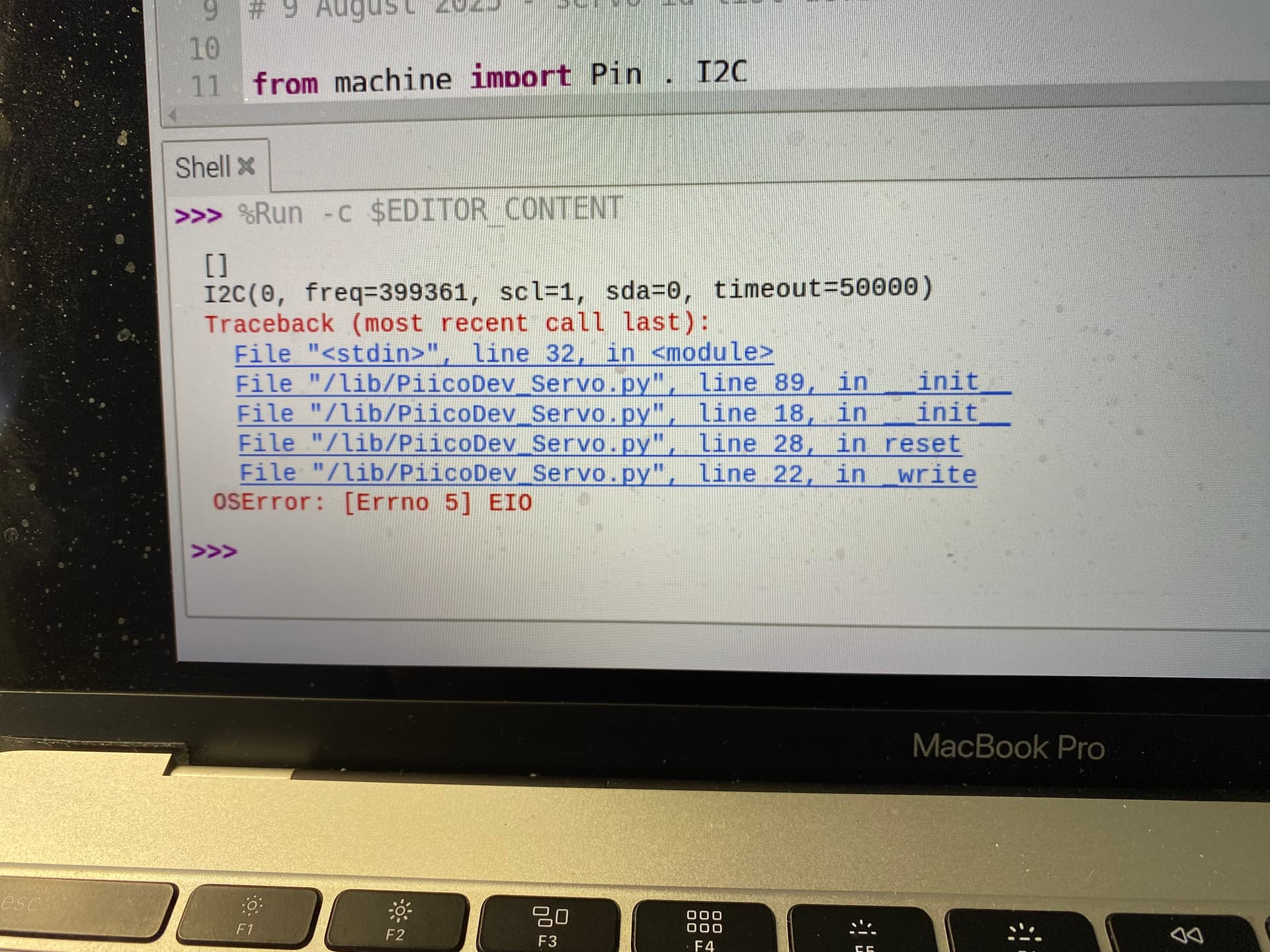
with the error messages:
File “” , line 32, in module. (line 32 is the controller definition line above)
File “/lib/PiicoDev_Servo.py”, line 89, in __init
File “/lib/PiicoDev_Servo.py”, line 18, in __init
File “/lib/PiicoDev_Servo.py”, line 28, in reset
File “/lib/PiicoDev_Servo.py”, line 22, in __write
OSError: [Errno 5] EIO
Can someone please identify the problem
Toni
1 Like
Hey @Toni135859,
It looks like your Pico isn’t able to communicate with the PiicoDev Servo Driver. This usually happens if there’s an issue with wiring, power to the board, or the I²C bus/address setup.
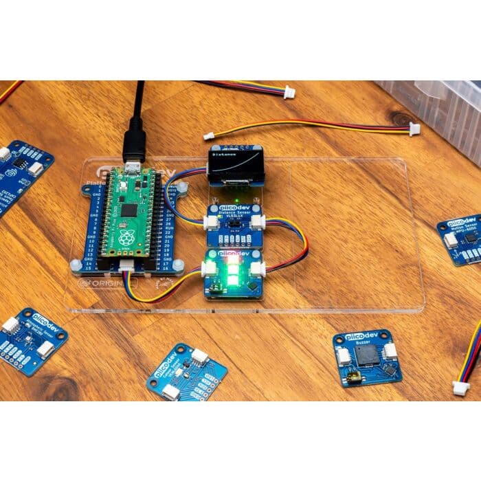
Could you share some photos of your setup while it’s powered up? That will help us check that everything is connected correctly and receiving power.

Hey @Toni135859 ,
That wiring setup looks correct to me!
Would you be able to share the code you are running when you encounter this error?
What is the best way to copy the code from the Pi/Pico combination to this forum which I normally access from my laptop and VNC viewer?
Hey @Toni135859 ,
If you can unplug your Pico from the Pi and connect it to your laptop, it will be detected as a USB device. You can go into this USB device and get the code from it this way.
I don’t have a lot of experience with VNC Viewer so I’m not sure if you can copy and paste between between the VNC Viewer window and the rest of the system but there may be a way to do that as well.
If you need, a screenshot of the code would also work if you can’t get another method to work for you.
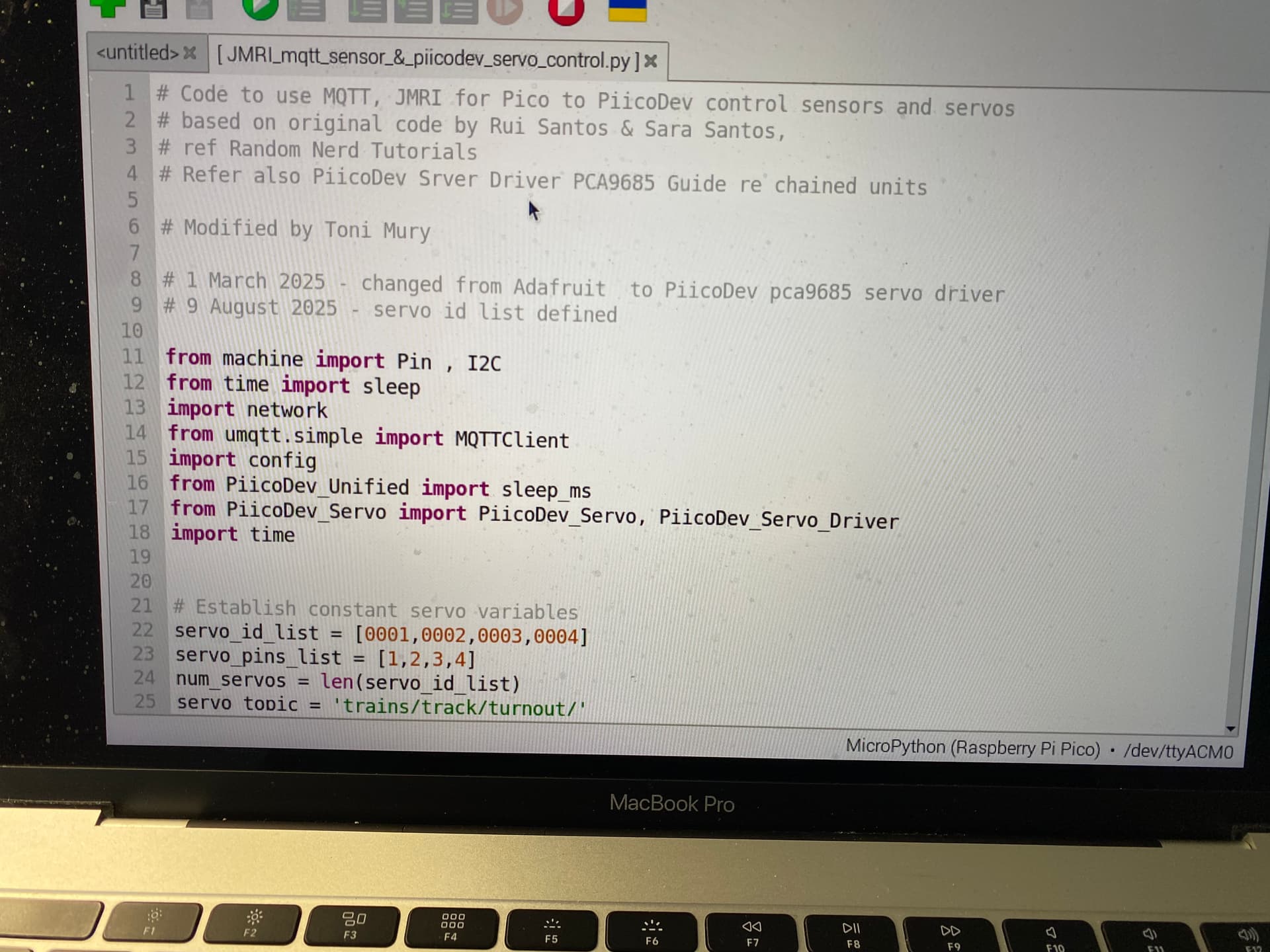
Hey @Toni135859,
Try changing your servo_id_list = [0001, 0002,0003,0004] to servo_id_list = [1,2,3,4] from memory, leading zeros in Python can cause some strange issues.
Have you been able to get any of the example code from here working? GitHub - CoreElectronics/CE-PiicoDev-Servo-Driver-MicroPython-Module
Hi Ryan,
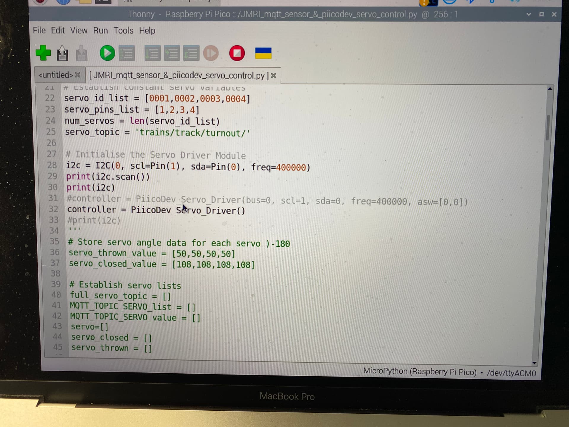
I have simplified the code as you suggested as shown below and am still getting the errors.

Toni
Ryan, Just another thought. Because the print(i2c.scan() is showing a result does this mean that the servo driver is not being found by the pico? if so could it be that the sda and scl pins are wrongly addressed in my software? What Pico pins are associated with the PiccoDev bus cables?
Toni
Hey Tony,
That looks to be the issue, the PiicoDev SDA/SCL is set up differently from the Default pinout that the Pico uses.
The Breakouts for PiicDev are SDA (GP8) and SCL (GP9) as seen on our Pinout Guide. A change there should be the fix you are looking for.
Cheers,
Blayden
Thanks Blayden
I just found that out a few minutes ago before I opened your post. I read the pinouts section of your PiicoDev guide!!!
As always it’s there in your documents if one looks hard enough.
Now to get back on with my project.
Cheers
Toni
2 Likes