Pimoroni Pico VGA Demo Base (PIM553)

This is a placeholder topic for “Pimoroni Pico VGA Demo Base” comments.

Built especially to showcase the low cost, feature-rich RP2040 chip on the Raspberry Pi Pico, this board has VGA output, an SD card slot, digital I2S audio output, and more!

Read more

Would any headphone jack work on this board? If not, what audio cable should I be looking for?

3 Likes

Any 3.5mm stereo cable (TRS) should work with this. like this one

3 Likes

I notice this product has links to the non wifi pico board.
I know there are some minor differences with the W and non W pins.
Will the demo software work with a Pico W?

1 Like

Hi there @David191372,

This should work absolutely fine with the Pico W. All the GPIO pins, which are the ones that connect to the Demo Base, are identical between the two versions. It’s only the positioning of the debug pins that are different, as seen below.

1 Like

Hi Jane,
That’s a great answer. That picture is worth at least 1000 words :slight_smile:
I already have the parts, now I need to make them do something fancy!
David

1 Like

Glad to hear it @David191372. Enjoy the project and happy making :slight_smile:

I have managed to compile Doom and get it running with a usb keyboard for input. I’m actually surprised how well it runs. The sound on the PWM port was terrible. I see the board has DAC chip built in. I’m currently working on getting Doom’s sound to play out the DAC port.

This is an interesting little board to play with. Next I’ll try and get Fuzix Linux to run on it :cowboy_hat_face:

1 Like

Hey @David191372,

Nice work getting Doom up and running! PWM audio is always a bit rough around the edges, and the onboard chip should give you way cleaner output once you’ve got it patched in.

Definitely keep us posted on your progress!

1 Like

How To Play Doom on a Raspberry Pi Pico 1

With VGA Graphics, USB Keyboard Support and Sound

Hello Again,

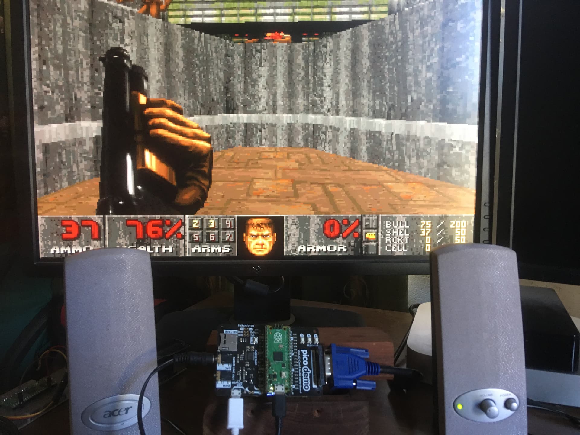
I managed to complete my little project. It actually works fairly well :slight_smile:
I of course don’t take the credit for porting this to pico. This was done by someone named “Bad-Spyro”. His git archive is listed below.

Below are some instructions on how you can install the image I built from that source onto your own Raspberry Pi Pico 1 and play Doom like it’s 1993.

This open source build of Doom runs directly on the Raspberry Pi Pico using VGA output and DAC sound — no DOS operating system required!

Hardware you will need

  • Raspberry Pi Pico (Version 1)
  • Pimoroni VGA Demo Board (PIM553)
  • VGA Monitor
  • USB Keyboard (with micro USB plug or adaptor)
  • Head Phones or Speakers (3.5mm Jack Plug)

Files You Need To Install.

The only two files you need are in the attached zip archive.
Pico-Doom.zip (1.6 MB)

  • doom_tiny_usb.uf2 Compiled doom code
  • doom1.whx Compressed Doom1.WAD data file

:gear: Step 1 — Install picotool

Both the .uf2 program file and the .whx compressed wad data file must be copied onto the pico.
You can simply drop the uf2 file onto the Pico but the only way get the data into the correct location is to use picotool. (I used version 2.2.0-a4 in case that makes any difference)

Here is how to download and install it.

:penguin: On Linux (Debian/Ubuntu)
sudo apt install picotool

:red_apple: On macOS (using Homebrew)
brew install picotool

:window: On Windows

  1. Download the latest release from:
    Releases · raspberrypi/picotool · GitHub
  2. Extract the ZIP and open a Command Prompt in that folder.

:electric_plug: Step 2 — Put Your Pico in BOOTSEL Mode

  1. Hold down the BOOTSEL button on the Pico.
  2. While holding it, plug in the Pico (not the PIM553 usb port) into your computer’s USB port.
  3. It will appear as a drive named RPI-RP2.

:floppy_disk: Step 3 — Flash the Doom Program

Copy the following file onto the RPI-RP2 drive:

doom_tiny_usb.uf2

The Pico will reboot automatically and disconnect.

:brick: Step 4 — Write the Game Data (WAD)

With the Pico still connected (but NOT in BOOTSEL mode)
(If this doesn’t work put it back in BOOTSEL Mode anyway.)

Open a terminal and cd to the same folder as the downloaded files and run the following command:

sudo picotool load doom1.whx -t bin -o 0x10042000

This writes the Doom data into flash memory at the correct offset and leaves the doom_tiny_usb.uf2 file in place.

:repeat_button: Step 5 — Reboot and Play

Power off the Pico
Connect the Pico to the PIM553 board matching the USB port to the correct end.
Connect a VGA Monitor.
Connect the Keyboard directly to the Pico, you may need a micro USB adaptor.
Plug in the 3.5 mm audio jack to the port marked “DAC”.
Connect power to the USB port on the PIM553 board.

Doom should start the demo automatically.

:puzzle_piece: Notes

  • These instructions are only for the original Raspberry Pi Pico (RP2040), not Pico w or Pico 2.
  • This build was performed with SDK 1.4 and Extras 1.4 (later SDK’s break compatibility).
  • If you want to completely erase the Pico and start over: sudo picotool erase

These files won’t run on later versions of the board like Pico W or Pico 2 as the newer boards require a different version of the C SDK’s (1.5 or 2.0?) and lots of things changed in those versions that required updates to the Doom source code. I used SDK 1.4 and Extras 1.4 to compile from the source, as that was current around the time Doom was ported to the Pico 1.
I only made minimal changes to the code to suit the PIM 553 layout where required.
Once I figured out which SDK/Extras to use the only other change was to the GPIO Pins that the DAC Audio chip is connected to. PWM sound was almost non existent among the static.

I2S_DATA_PIN=26
I2S_CLOCK_PIN_BASE=27
BCK=27 and LRCK=28

If you really want to build your own from source here is the download command.
git clone https://github.com/Bad-Spyro/rp2040-doom.git
It took me a lot of “ChatGPT’ing” to get it compile and run :slight_smile:
Many rabbit holes were entered.

Send me a message if you get it to work!
Have Fun

David.

2 Likes

Cheers for the write-up @David191372,

Been wanting to give this a spin for a while for some fun, might follow your notes!

1 Like

Hi Guys,
I’m still playing with my PIM553 and I’m currently trying to install Fuzix (Linux) on it.
I got very close to get it to boot off the internal flash but apparently there is internal flash flakeyness.
I’m looking for a C demo that shows how to us the SD card on this board. Just a simple write and read file would be a huge head start.
The pico-playground demo code linked to this products page doesn’t seem to address the SD Card slot use at all. From what I can figure out it doesn’t use the standard 1-bit SPI mode it uses 4-bit SDIO mode hence the pin assignments like this.
SD_CLK → GPIO 5
SD_CMD → GPIO 18
SD_DAT0 → GPIO 19
SD_DAT1 → GPIO 20
SD_DAT2 → GPIO 21
SD_DAT3 → GPIO 22
I need to learn how this interface works and a C demo program would be invaluable.
Odd that Pimoroni have a demo for most of the other features of this board but not the SD card that I can see.
Thanks
David

1 Like

@David191372, thank you for introducing me to Fuzix.

These the two statements from its missing features made me fall in love with it:

  • TCP/IP (in progress)
  • Support for > 32MB filesystems (but first figure out how to fsck a giant fs on a slow 8bit micro!)

I am going to have to get this going on something.

I wish I had some knowledge of C demo Code for the Demo Base as an exchange for this momentous gift.

Hi Jane,
My quest for a demo C program has progressed. It’s not quite ready yet but I’ll post it where when it is. I will post it here and perhaps start a new thread for my Fuxiz build project.
One deep rabbit hole ChatGPT lead me down was pointing me at an old probably abandoned Fuzix project fork.
Don’t use this one “https://github.com/davidgiven/FUZIX

I spent a lot of time trying to get it to build with no success but it wasn’t all time wasted. I got lots of practice :slight_smile: relearning skills that have laid dormant for many years.

I think many of the problems you mentioned have been solved in this active fork.

I think the fork uses a new “Fuzix Filesystem” that is not limited in size. Well not limited it ways that would concern Fuzix :wink:
Interestingly I could not get this Fuzix version to boot from the Pico internal NAND flash storage.
Something to do with the Fuzix implementation of wear balancing for the Pico internal flash storage being unstable. I thought not to worry I’ll just boot from the SD slot which is already on the PIM553.
I’m currently working on testing the built in SD Card reader. Something to do with the PIM553 using 4bit SD interface where fuzix is built to use a single bit interface.

2 Likes

Hi Everyone,
Its time I shared what I have learned about SD cards and how we can connect to them.
I have limited my testing to C code to fit in with my Fuzix plans.

After working with my mate the Information Cannon, (Chat GPT) I have concluded that this card slot is virtually if not completely unusable on the PIM553. I’m happy to be corrected if I’m wrong.

My Findings
There are two modes of operation of these little SD card slots, SPI mode and SDIO mode.
This board (PIM553) is wired to use SDIO mode.

I found these drivers and examples online.
no‑OS‑FatFS‑SD‑SDIO‑SPI‑RPi‑Pico — GitHub repository by Carl John Kugler III
https://github.com/carlk3/no-OS-FatFS-SD-SDIO-SPI-RPi-Pico
The drivers seem extremely well written and I later got a demo to work on a breadboard without the PIM553.

SDIO MODE

SDIO mode used the following pins. (on the PIM553)
SD_CLK → GPIO5
SD_CMD → GPIO18
SD_DAT0 → GPIO19
SD_DAT1 → GPIO20
SD_DAT2 → GPIO21
SD_DAT3 → GPIO22

SDIO mode uses 4 data bits in parallel so its much faster than SPI with 1 data bit, which makes it a better choice but it’s more demanding on the hardware.

The driver expects / requires a specific layout of the GPIO pins.
The connections can be to different pins but the location of the pins to each other is fixed.
If you start with DAT0 then
DAT1 is DAT0 +1 pin.
DAT2 is DAT0 +2 pins
DAT3 is DAT0 +3 pins.
CMD is DAT0 -1 pins
So far so good I hear you say but here is the show stopper.
CLK required to be DAT0 -2 pins so that would need to be GPIO17 for this driver to work but but it’s not its on GPIO5 on the PIM553.
I also hear you say. They are just coded numbers, why not change them in the code.
From what I can tell they need to have this adjacent pin layout for speed and stability.
They are hard coded in assembler code and I didn’t feel like playing in there.
So as there is no way I can think of to physically move the connection from GPIO5 to GPIO17 as well as the fact that GPIO17 is already used by VGA VSYNC, I stopped trying SDIO here.
I gave ChatGPT a grilling to arrive at these results after going down many many rabbit holes.
Perhaps there is another driver around that works differently but I couldn’t find it.

SPI MODE

SPI mode uses the following connections. My understanding is this board also can’t do SPI as there is no connection for CS or (Card Select). This signal activates the card.

MISO → D0 GPIO19 (maybe) Data
MOSI → CMD GPIO18 (maybe)
SCK → CLK GPIO 5 (maybe)
CS → Here is the problem I see no possible connection for Card Select exposed anywhere on the PIM553.

So from this I think SPI mode is not useable on this PIM553 card.
I say maybe for each of the connections as it’s not documented anywhere and I can’t test anything.

Stand Alone Test

To prove the drivers actually work and ChatGPT can actually figure this crap out I used my little stand alone SD Card Slot on a bread board. Connected to my pico as follows. Then I could read and write data to a FAT File System in SPI mode. I chose this mode with a view to my Fuzix project as it is configured for SPI mode by default. I plan to mount the root filesystem on the SD.

My stand alone SD card has no documentation and no markings at all. (YAY)
This is what I figured out. With the SD card on the underside of the board and the pins away from me.
See pic below.

Left to Right. Connection in Demo code
Pin1 = +3.3v
Pin2 = CS GPIO5
Pin3 = MOSI GPIO3
Pin4 = SCK GPIO2
Pin5 = MISO GPIO4
Pin6 = Gnd

I then modified the “simple example” from the drivers to write and read a file.
sd_driver/examples/simple/main.c
This won’t work on the PIM553 but If you just want to test your bread board setup here is the UF2 file.
It is built for the Pico W and I doubt it will work on a plain Pico.
It flashes the LED 3 times giving you time to start your console and outputs diagnostic stuff as it reads and writes data to the SD.
If you don’t have a console stick the SD into a PC you will see files have been written to the root folder.
From the sample I have included the files I modified in case you want to build your own other wise just flash the UF2.

SPI Demo.zip (254.2 KB)

I hope this actually helps someone avoid wasting time on the PIM553 sd card slot as I can’t see a way to get it to do anything.
David

1 Like