This is a placeholder topic for “RP2040-Zero, a Pico-like MCU Board Based on Raspberry Pi RP2040” comments.
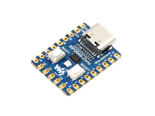
RP2040-Zero, A Low-Cost, High-Performance Pico-Like MCU Board Based On Raspberry Pi Microcontroller RP2040…
Read moreThis is a placeholder topic for “RP2040-Zero, a Pico-like MCU Board Based on Raspberry Pi RP2040” comments.
RP2040-Zero, A Low-Cost, High-Performance Pico-Like MCU Board Based On Raspberry Pi Microcontroller RP2040…
Read moreThis board seems to support CircuitPython but not Micropython. Is this correct?
Mine seems to work ok using programs written in MicroPython.
Hi Omar,
Any RP2040 board with the recommended >4MB of flash will be able to run micropython perfectly.
In short this board does support it!
Can you share a few project that you did with this board?
A very compact board, pity there isnt a PiicoDev/Qwiic connector!!
BTW, pinout for GP9 labelled I2C1 SCL, should be I2C0 SCL.
Tim
Thank you all for your input which made me try harder! I was trying to use Thonny to install micropython via the interpreter setup page but for some reason could not get a stable installation. In the end I set the RP2040-Zero to download mode and did a drag and drop of 20/12/2022 RPiPico UF2 and it worked perfectly first time. ![]()
Free Pascal works on the Pico, compiles faster than C/SDK or Arduino too.
The Pico Zero has a single WS2812 and Michael’s example worked fine.
The easiest way to install is grab fpcupdeluxe, works on Windows and Linux not Pi’s yet. Make a Pico folder and install the Pico tools there.
I have ported a few Piicodev boards to Free Pascal.
The reassignment of i2c pins was not too hard to figure out.
Hi Tims,
Good spot! I had to look twice to notice that the bus number was wrong when skimming the pinout.
This isn’t an exact replacement for the RP2040-Zero but Adafruit have a QT Py board that uses the same RP2040 chip that does feature a PiicoDev/Qwiic connector.
The QT Py is a good alternative but pricey in comparisom.
The CE write-up details the memory as 4MB of SPI Flash, but the Adafruit url as 8MB?
But if I understand correctly, the Pico-W only has 2MB of on-board Flash memory, am I comparing apples with apples?
Hi Tim,
Good catch! I’ll mark this as something that needs updating, it seems Adafruit have quietly upgraded the flash chip.
Yep! Both the RP2040-Zero and Pico (W) have 2MB of flash, so you can be confident that most projects will fit on anything with equal or more than that. More flash just means that you can put more code and libraries on at one time. The RP2040 actually supports anything up to 16MB IIRC!
This board has a problem with high I2C clock rates. 100khz is ok not 400khz.
Found this when I tried to use it with a Piicodev OLED.
The OLED needs I2C 400khz to draw the screen correctly, at 100khz the pixels are distorted. Probably because the screen does not get loaded quickly enough.
Running the RP2040-Zero I2C at 400khz; i2c.scan() shows the devices correctly but if you try to use them it responds with cannot communicate. If the I2C clock is dropped back to 100khz the devices work ok except for the OLED, the screen is distorted. Using the same code on a Raspberry Pi Pico works fine.
Guess I wont be using the OLED with the RP2040-Zero.
cheers
Jim
Hi Jim,
Great findings, it would be great to see those edges on an oscilloscope - I wonder if inline 120 ohm resistors might be able to save the higher clock speeds.
The PiicoDev adapter for Pico needs them because the Pico’s outputs have a very steep edge when toggling their IO.
I’ve added a note for the team to update the product page ![]()
Liam
I really like the small form factor of these boards. However it is a shame that the SWDIO and SWCLK programming pins are not brought out to pads or a connector on this board. Even some tiny pads that I could solder onto to attach a picodebug probe for debugging would really help with C++ development. If you are re-spinning this board then please consider some pads on pins 24 (SWCLK) and 25 (SWDIO).
Hey @Denis92790, welcome to the forums!
That is a very good idea and would add a lot of extra functionality to this board.
I would consider reaching out to the manufacturer with this feedback at this link, I’m sure they would be interested in it.
Best of luck with your future projects! ![]()
I think Waveshare did an excellent job cramming all the pins they have onto this tiny board. If you look closely at the processor where pins 24 (SWCLK) and 25 (SWDIO) are, you will see it would be extremely difficult to break these pins out without removing other functions. And … this board has other limitations probably caused by trying to make it as small as possible.
As this board is very similar to a Raspberry Pi Pico, except for ADC3, why not use a Pico to develop the program then transfer it to this board when debugged. Waveshare is not going to change this board unless addition of debug pins will result in many additional sales. I have never found a use for the debug pins anyway. These type of microcontroller are not designed to perform complex tasks.
If you still think this is a viable change, suggest you contact Waveshare.
Regards
Jim
Hi There,
I’m wondering how the power consumption on this little board compares to a regular sized (non wifi) pico. Is it going to be similar simply because it’s the same processor? Also are low power / sleep modes also the same on both devices? I’ll be using Micropython.
Thanks
David
Running blink program measured 22mA, about the same as a Raspberry Pi Pico.
No noticeable difference, same processor same software.
One difference I found is the maximum I2C frequency. The Raspberry Pi Pico has a better track layout with more GND connections and can run at 400kHz ok. (PiicoDev OLED needs this speed to work properly) I could not get this board to work at 400kHz. Maybe it was my setup, need to test this again I think.
There is no separation between USB 5V and the 5V pin, like on the Pico. If you use USB to program be sure to remove whatever supply you have connected. (ie 3.7V LiPo or such)
The schematic says 5V but it will happily work off a 3.7V LiPo.
Cheers
Jim
EDIT: OLED not working at 400kHz, INCORRECT.
Tested it again and it works fine, no idea why it didn’t in the past, may have been my setup.
Hi @David191372,
As James has stated, there are likely no functional differences. Thanks for testing it empirically @James46717, huge help! Thanks for the heads up regarding the 5V rail connection as well, that may save someone.
Regarding the I2C frequency, it does make sense that this board struggles more. However, if this is the case, I’ll change the description of the item to include this info. I’ll see about testing one of these with the PiicoDev OLED to confirm.
Let us know if you have any more questions @David191372!
@Zach Tested the OLED with the RP2040-Zero and it works ok now.
No idea why it didn’t in the past. Probably the setup I was using or I had damaged the board.
Cheers
Jim
PS New RP204-Zero and OLED.
And you can get our latest projects and tips straight away by following us on:
![]()
![]()
![]()
![]()