Hi guys,
Background
I was hoping to keep a lid on this project until I had a bit more to show, but I need a hand. I’ve constructed some temperature sensors that communicate over RS485 using the ATtiny202 and excellent TMP117 as part of a larger project, and my current hurdle is setting the baudrate on the UART.
Here’s the schematic and photos of the boards.

The two bottom boards are the ones in question, the top one is a “master” designed to sit on a raspberry Pi.

The problem
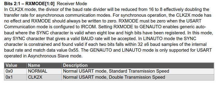
The ATtiny datasheet gives the following guidelines for setting baudrate:

Full datasheet here:
Since I’m trying to implement Modbus-ASCII, I’m targeting a baudrate of 19200. 9600 must also be supported but that’s a problem for later since I haven’t even gotten 19200 to work properly yet.
My attempt
Here’s what I have so far:
My clock speed (and hence CLK_PER) is 10MHz I believe according to what I’ve set.
This means my calculation is:
BAUD = (64 x 10,000,000) / (16 x 19200)
This comes out as:

2083 in hex is
0x0823. My thinking now is that I need to put 0x08 in the BAUDH register, and 0x23 in the BAUDL register.
The code
Here’s my code so far. I mistakenly picked the 2K flash variant of this chip, which made it far too small to fit the excellent megaTinyCore. This means I had to do it closer to bare metal. Here’s the tutorial which got me started if you’re interested. Like most “hard ways” it’s giving me more pain, but more fun and learning.
#include <avr/io.h> // header file containing all the structs and their registers for interacting with peripherals
#include <util/delay.h>

#define PIN_TXD  6
#define PIN_RXD  7

void synchronousWrite(uint8_t byteToWrite){ // I commented out most of this while troubleshooting while I sort out baudrate
    USART0.TXDATAL = byteToWrite;
    // while (!((USART0.STATUS & USART_TXCIF_bm) && (USART0.STATUS & USART_DREIF_bm))){} // wait for transmit complete flag
    // USART0.STATUS = USART_TXCIF_bm; //
}


void main() {
    // Setting clock speed needs to use the protected write macro
    _PROTECTED_WRITE(CLKCTRL.MCLKCTRLB, 0x1); // Enable prescaler, prescaler register is 0, should lead to 10MHz clock (safe for 3.3V)

    //Setup serial
    //TXD is PA6, RXD is PA7
    PORTA.OUTSET= (1 << PIN_TXD);
    PORTA.DIRSET = (1 << PIN_TXD);

    USART0.BAUDH = 0x08; // supposed to be 19200 baud
    USART0.BAUDL = 0x23;


    USART0.CTRLB += USART_RXEN_bm; // Enable receiver
    USART0.CTRLB += USART_TXEN_bm; // Enable transmitter
    USART0.CTRLC += USART_PMODE_EVEN_gc; // turn on even parity (part of modbus spec)

    _delay_ms(10000); // Wait 10s after programming (reset) so I can get logic analyzer probes onto the board

    while(1){
        _delay_ms(100);
        synchronousWrite(0x55); // send 0x55 10 times a second. 0x55 is a bunch of alternating 0s and 1s, so great for measuring baudrate
    }
}
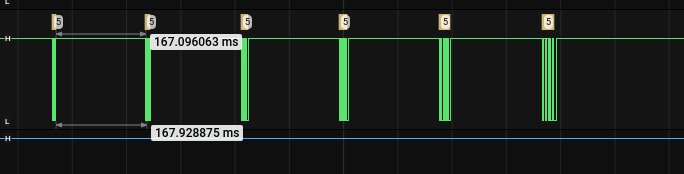
But it comes out on a LA as below:

That frequency of 5.7KHz means my baudrate is twice that, 11500 baud or thereabouts.
Can anyone see where I’m going wrong? I get that this is a very deep dive into something no engineer would do, but after a few days of banging my head against this wall, I’m stumped!
Feel free to hit me with as many clarifying questions as you like
Cheers,
James